Mike T; may the Master Smith that watches out for us all keep a special eye on you. a co-worker just had that and his doc found cancer.
when i was growing up in arizona, we took a long excursion ride in the White Mountains. 2 big steam engines, can't remember the type. got hooked on 'em then. some of my kid years was spent in a mill town called Standard, and logging trains still ran along with trucks. diesle fired steam was the last i remember.
you might look up Westside-Cherry Valley Railway. i'll see if i can find website and pass it on.
|
|
- bam-bam
- Tuesday, 02/01/11 00:32:48 EST
|
Mike T; check abandonedrails.com....also wikipedia has some stuff
|
|
- bam-bam
- Tuesday, 02/01/11 00:48:44 EST
|
POWER HAMMERS
Looking thru some books, as well as the JYH info, thinking of a different direction. a trip hammer system seems to have gotten my curiosity. any thoughts from anyone? i'm gonna have more room after this storm-forced repair, but don't want to put effort into a bad idea
|
|
- bam-bam
- Tuesday, 02/01/11 01:00:16 EST
|
THANK YOU, THANK YOU. I've been able to loosen up a lot of rusted tight garage sale tools after reading how on here.
Soak them with Blaster spray, then vibrate. I use a hand held air chisel with a ground round end bit to vibrate and loosen.
|
|
Carver Jake
- Tuesday, 02/01/11 02:17:52 EST
|
Bam-Bam What do you mean by "trip hammer system"? Virtually all mechanical hammers are called trip hammers as a generic term.
|
|
- guru
- Tuesday, 02/01/11 13:54:30 EST
|
Westside/Cherry Valley RR has been dead for years. It was started as a tourist RR as part of a pie-in-the-sky amusement park development. Went bust. Some bottom-feeders bought the property and also went bust, but only after they removed the rolling stock. The local Mi-Wuk Indians have bought the property using profits from their casino, plan to build housing on it.
Standard (the town) was bulldozed by the property owner 30? years ago and is no more. The rails in the woods have been gone even longer.
Been a long time since you were in Tuolumne County, eh?
David Hughes
|
|
- David Hughes
- Tuesday, 02/01/11 15:36:12 EST
|
Trip Hammer; I realized that awhile after posting. Should have said Helve Hammer. Enough of my projects need space all around, not just left,right, operator sides. gravity fall, spring assist if needed. A long shaft, or "helve" from the research done would compensate to a point for direct powered force.(did i say that right?). It would also allow work room around the "anvil". My shop space is limited to a "2 man space" if they know what they are doing. I can't really draw with my program, so i can only try to picture with words. I will have an odd corner in my new floor plan. From that basicly 90 degree corner, projecting out at a 45 degree to my "heavy" anvil was my idea.
|
|
- bam-bam
- Tuesday, 02/01/11 15:55:42 EST
|
bam-bam,
Given that scenario, maybe you could just make yourself an Oliver hammer.
|
|
- Rich
- Tuesday, 02/01/11 16:03:06 EST
|
David Hughes
no, it hsan't been a long time. I have lived here for over 30 yrs. before that, took summer vacations here. married into a family whose members surveyed some of the rail beds, or were the "engineers" on the engines. they worked the Westside-Cherry Valley and some worked the Sugar Pine.
I lived awhile in Standard in the '60s while my dad worked in the Pickering Lumber Co. sawmill.
Westside Railroad hauled logs to the Westside mill starting in the early 1900s. My wifes' grandfather used to "skid" logs to the loading "donkeys" in the woods using a team of mules. some of my "ancestry" goes to 1851 in Tuolumne County
|
|
- bam-bam
- Tuesday, 02/01/11 16:16:45 EST
|
Rich; pardon my lapse in knowledge, what's an Oliver hammer? not seen that one in my looking, that i know of.
|
|
- bam-bam
- Tuesday, 02/01/11 17:00:04 EST
|
Mr. Hughs, it also sounds like you live in Tuolumne County or used to. there are many people here that haven't heard or learned the whole story. for many years the powers that be have promoted tourism and just about everything that goes with that, at the cost of the real history of this area. now i will climb down from my anvil shaped soap box.
|
|
- bam-bam
- Tuesday, 02/01/11 17:21:57 EST
|
Rich, went a different search route, still no picture of what a "true" Oliver is, but someone says an Oliver is the same as a Treadle. this is the direction i was thinking, but with a bit more "modern" twist.
|
|
- bam-bam
- Tuesday, 02/01/11 17:58:28 EST
|
IF you google- BLACKSMITH OLIVER HAMMER- there are pages of pictures of true oliver and early treadle hammers
|
|
- Ray Clontz
- Tuesday, 02/01/11 18:37:36 EST
|
Guru, if i do go ahead with this hammer idea, could there be patent problems? it is for my own use, and due to the 'limits' already reached in this area, that 'scary to me' question came to mind.
|
|
- bam-bam
- Tuesday, 02/01/11 18:41:52 EST
|
Patents? No problem unless its a new patent in the last 15-20 years. They expire in 14 years, sooner now days if the inventor doesn't pay the patent office to "maintain" his patent.
I have a design sketch for a helve hammer that is cam operated and spring balanced. The operator presses on the the treadle pulling the balanced helve down toward the work and the cam. The cam raises and drops the helve and the operator can feather the blows according to how hard he leans on the treadle.
The cam and motor need no clutch as the helve is disengaged by being lifted off the cam. The operator can feather the blows which is something that cannot be done on a standard helv and cam hammer. The operator powered spring also increases the downward velocity so the hammer hits harder than a simple gravity drop. It is also simple to build.
The important thing about a helve is that the beam must be stiff and not wobble right and left. So a "T" shape at the pivot spreading the bearings apart is advised. An "A" frame beam with the bearings at the feet of the A would be best.
The mass of the hammer should be a bit higher than an equivalent power hammer because helves, even with spring assist move slower. You also want a short lift to get rapid blows.
I couldn't find my drawing in the anvilfire files so I probably haven't ever scanned it. But if you are interested in building it I can make new sketches.
|
|
- guru
- Tuesday, 02/01/11 19:22:11 EST
|
bam-bam,
No patent issues - the idea is public domain now.
|
|
- Rich
- Tuesday, 02/01/11 19:23:01 EST
|
Even with patents, you are free to build one for yourself IIRC.
|
|
- grant - nakedanvil
- Tuesday, 02/01/11 19:50:47 EST
|
no patent issues so here goes. Guru, i'm VERY interested. was thinking A frame style headframe,and a double pivot for the helve. the verbal pic goes like this.... take the letter A, put the bearings at the 'foot' of each leg. now take the letter T and invert it on the A with both horizonal lines together and the leg of the T extending thru the apex of the A. now stick the hammer on the end of the leg.
|
|
- bam-bam
- Tuesday, 02/01/11 20:25:21 EST
|
Mr. Bam: Yes, I was born and raised in Columbia, 4th generation, graduated from Sonora High and all that. My dad worked for Pickering when the sawmill was in Sonora. I know all about the Morons who "interpret" the history in Columbialand Park. Bought land outside Columbia (Columbia got too crowded), built a place there, and plan to be the resident Curmudgeon as soon as the current ones retire. My anvil and tools are out of a Columbia gold rush blacksmith shop, when the smith retired, he gave his tools to my grandfather.
Yes, Westside Lumber Co had a logging RR. I thought you were talking about the tourist RR, built (on a portion of the old bed) by Glen Bell (founder/owner of Taco Bell, that is where the Bell came from--and you thought it was a cute advertising ploy) as part of his Tuolumneland Park. I remember when the Westside mill burned (1962?), during the strike, we went to go see the ruins. Tuolumne City was never the same after that, quoth the Curmudgeon.
David Hughes
|
|
- David Hughes
- Wednesday, 02/02/11 00:45:08 EST
|
David, thank you for clearing the air. maybe sometime we'll meet over the anvil.
|
|
- bam-bam
- Wednesday, 02/02/11 02:02:53 EST
|
NEW Miniature Anvil Collections
I've been working on these for over a week. Enjoy!
|
|
- guru
- Wednesday, 02/02/11 02:20:57 EST
|
Thanks bam bam, colonoscopy showed one polyp, removed it, have a slight case of diviticulosis. Modern medicine has gone a long way. I have a series of pictures that the camera took as it made its journey through the colon. Everyone needs this done. It had been 20 years since my last one. Shouldn't wait so long. AND for all the guys on this web site...get a PSA test every year for your prostate. Drawing a little blood can save your life. One of my kin folks just passed away from prostate cancer, a PSA test may have caught it in time.
|
|
Mike T.
- Wednesday, 02/02/11 04:21:25 EST
|
Guru, I've got about 10 miniature anvils, but nothing remarkable. Are you selling the Anvilfire miniatures?
|
|
Carver Jake
- Wednesday, 02/02/11 11:33:24 EST
|
Jake, IF and WHEN I make them, yes I would be selling them. I know sort of what I want but it needs to be first class. Some of these items sold as "collectibles" in recent years have lost value over their original price.
|
|
- guru
- Wednesday, 02/02/11 12:36:27 EST
|
You mean my Finken Mint Commemorative Confederate Teacups are worthless? I'm ruined! ;-)
|
|
Bruce Blackistone (Atli)
- Wednesday, 02/02/11 16:01:01 EST
|
Yes Bruce, but only because you bought the damyankee cornflower blue instead of the proper Confederate gray. I'd have thought surely you knew better! :-)
|
|
- Rich
- Wednesday, 02/02/11 17:26:38 EST
|
Don't laugh. My late Uncle bought dozens of those goofy molded almond shell and resin "collectible" figurines as an investment. . .
|
|
- guru
- Wednesday, 02/02/11 18:12:37 EST
|
First off, Thanks for answer all the previous answers to my questions. The people on this fourm are very knowlegable. Anyways, I had another question. Quite a while back someone on this fourm was talking about an old method used for making threads before lathes, taps, dies and such. It was an interesting technique that involved brazing and other things. Last time it was talked about I didn't really understand. If anyone can give me some info or point me in a direstion I would like to learn more about this technique. Thank you.
|
|
RM Howell
- Wednesday, 02/02/11 23:08:54 EST
|
RM, Making threads by brazing was used to make large power screw nuts such as for vises, presses and so on. The method below is an approximation.
Step one was to make the male thread. This was done on a lathe of the time using hand tools and hand laid out threads. The shank was prepared, then scribed in a thread spiral by one of several methods. Then the threads were cut a little at a time following the scribed lines. This was a tedious task that produced rapid development in lathe feeds and mechanisms during the early industrial revolution.
Once the screw was made a tube was made (by forge welding flat stock around a mandrel) and fitted around an arbor. If may have been reamed or bored out to smooth strait bore a little larger than the screw. Then the threads were made by forging bar stock to fit the threads in the screw and wrapped around the screw to fit. When this coil spring shape fit the tube and screw it was then "spelter" brazed into the tube in the forge. The inside of the tube and out side of the thread was scraped clean, then powdered brass and a paste binder or flux, or perhaps brass wire was used to sweat braze the tube and thread coil together.
This method was used to make tens of thousands of vises until internal threading was developed. That was when Peter Wright started selling their patented "solid box" vises with a one piece nut or "box".
|
|
- guru
- Wednesday, 02/02/11 23:52:24 EST
|
Four articles about leg vise restoration are in "Anvil Magazine" hard copies, Aug, Sept, Oct, Nov. 2001. In Part 4, November, the brazed thread in its box is shown.
"Restoration of Leg Vises; Parts 1,2,3,4; Volume 26, Numbers 7,8,9,10. By James R. Melchor and Peter M. Ross. Photos by James R. Melchor
|
|
Frank Turley
- Thursday, 02/03/11 10:55:48 EST
|
Leg Vise & Post vise; got 4 awhile back, newest 30yrs. old i am told. 3 others look like the came around the horn on a clipper ship. have not seen i.d. marks yet, but they do need to be cleaned up some. any tips to help me with identification?
|
|
- Keith
- Thursday, 02/03/11 21:04:24 EST
|
Keith, less than half the leg vises I've seen had any markings on them and only one out the six I've owned had any markings other than a size number. The marked one is an old English Brooks and Cooper (Mousehole Forge). The marking is on the nut or box and wraps on the curved surface, a difficult thing to do.
|
|
- guru
- Thursday, 02/03/11 22:31:20 EST
|
More Vise ID:. Keith, see our Leg Vise FAQ for a little more information. I'm sorry we do not have more or better photos. These long slender items are difficult to show well.
Generally but not always, the old English vices have more fine touches than later American made vises. The English vises have turned decoration in the form of lines cut into the boxes (nuts) and screws. The brackets are hand forged in various styles and if the vice has the original spring it may have a delicate fish tail that fits around the edges of the front leg. The legs often have heavy chamfers on them sometimes to the point of make it square rotated 45 degrees to the rest of the bar.
Generally American vises have drop forged parts. Some have die numbers or weights marked on them and some the manufacturers name.
Leg vises were also made in other countries but few have made it to the U.S. French leg vises typically have side plates riveted to the leg and the front jaw pivots on and is guided between the plates. Their bench brackets are also different.
|
|
- guru
- Friday, 02/04/11 09:33:06 EST
|
Keith, If you PM me with photos, I can perhaps help you with vise ID.
|
|
Frank Turley
- Friday, 02/04/11 11:06:55 EST
|
Guru, Frank; thanks, i'll look at pics on file. don't have digital camera and every penny counts right now, but i'll see what i can do.
|
|
- keith
- Friday, 02/04/11 15:38:51 EST
|
vises...believe i have a peter wright style with a fish-tailed spring and a cast bracket. leg and such almost octagon, very nice work. my thinking is u.s. made. the other is 1"x2" tapered bar. turns to round below pivot,all tapered fairly nice.no spring, bracket or wear marks. jaws are 5", no plates, just plain. measures 43" total. the P.W. style is 41" total with 4 1/2" jaws and forge-welded steel faces.
|
|
- keith
- Friday, 02/04/11 17:26:32 EST
|
in addition.... last one in question is JUNK. will probable repurpose what i can. the P.W. style has a number "3" stamped inside the body just below the jaws. it is on both sides.
|
|
- keith
- Friday, 02/04/11 18:27:57 EST
|
Is the "3" stamped INTO or raised? Raised letters indicate drop forging, not open die or hand forging. I've only seen that on US made vices. Newer industry, newer machinery.
Due to blacksmiths vises being so similar most of the parts are interchangeable on vises the same size. However, with them coming in small incremental sizes and many of the parts being proportional there is a lot of variety.
If the vise is REALLY scrap, they are often wrought iron. More than $1/lb. scrap. . .
|
|
- guru
- Friday, 02/04/11 20:23:41 EST
|
Guru; stamped INTO. Moved the tagged as junk vise into the project corner, the one for looking to make work again. it's in real rough shape.
|
|
- bam-bam
- Friday, 02/04/11 20:30:04 EST
|
While pieces of old vise frame (or anvils) may be too big for you to forge they can be cut up OR if larger pieces are needed the wrought is excellent to be forge welded together. Its not the kind of scrap a smith should part with. .
Note that the jaws of leg vises are faced with hardenable steel. Springs on a wrought vise are probably steel and other parts may not be wrought as well.
|
|
- guru
- Friday, 02/04/11 21:23:44 EST
|
if you saw my junk pile..... i don't throw metal away. if it is wrought, will confirm tomorrow, it will be booby-trapped. good sized pieces of it are hard to get where i'm at.
|
|
- bam-bam
- Friday, 02/04/11 22:02:42 EST
|
I remember my grandpaw telling a story about the old days. He said there was a bridge beam that has snapped apart. He wondered how they were going to repair it. He said they got the old coal forge and aligned both ends of the beam over it. When it got up to welding temperature, a man stood at each end of the beam with a sledge hammer. A man stood in the middle and he would raise his arms then clap his legs. When he raised his arms the men would raise the hammers, when he clapped his legs, they hit each end of the beam. By using this timing method, they welded the beam back together. I think old stories like that are very interesting. I had an old friend named Mr. Shafer, he was in his ninties at the time, but he still carried an old business card that said steam irrigation engineer. Can you imagine using a steam engine to irrigate a crop ? He fought in World War 1, and marched across France and Belgium, he went to the top of the Eiffel tower, he said the tires on all of the army trucks were made of solid rubber ( pneumatic tires had not yet been invented ). When I was a boy, an old neighbor of mine had fought in WW1, he only had a half of a lung because he had breathed mustard gas, the old feller still smoked and rolled his own cigarettes. I always tried to glean as much information as I could out of these old timers before they died and took all that information to the grave. Did you know if a Model T was low on gas, you couldn't drive over a hill ? You had to turn around and back over a hill because the gas flowed instead of being pumped. In the Model A days my grandpaw always carried Prince Albert tobacco cans with him. Model A's didn't have rod bearings, they had shims. When a shim would wear out, he would pull over, cut some shims from the Prince Albert can, take the rod caps off and replace the shims. I could go on and on, but I bet there are a lot of old blacksmith stories that could be told if you could just find the right old timers to talk to.
|
|
Mike T.
- Friday, 02/04/11 22:38:56 EST
|
Old Stories: Some old stories are great, and some are just stories. The trick is finding the truth of the story.
Almost every old hammerman or industrial smith will tell you the story of the fellow that would demonstrate the control of a multi-ton power hammer by putting a pocket watch on the lower die then touching it with the hammer enough to make it wobble. Then he would show the onlookers that it still ran, replace it, and then WHAM! Make dust and metal foil out of it. . . The story teller would say HE knew the guy that invented the trick. . .
The trick was real. But the inventor of the trick and the fellow that probably did it more than anyone else was also the inventor of the steam power hammer, James Nasmyth. He was famous for his demonstrations and always kept a few old pocket watches just for the purpose.
Back around 1988-89 a fellow I knew came to me with HIS theory about why there are so many old anvils in the South with missing horns. He was looking for evidence to support his theory that Northern sappers set out to destroy the enemy's industry and economy would seek out blacksmith shops and break the horns of anvils to make it difficult to work and thus reduce their ability maintain tools, weapons and transportation. It was a theory, he had no proof.
I made the mistake of telling Jim Paw-Paw Wilson the story and he proceeded to start telling the story as history at civil war reenactments all over the county. Now people including those working as historical reenactors tell the story (because its a GOOD story) as history. It is not, it was a theory and nobody has proven it.
A TRUE story. . . Daryl Meier would make "26 cent pieces" on his Nazel 3B buy setting a penny on top of a quarter and sinking the penny into the quarter with a single blow and leave the coins readable and recognizable. He would sell the coins at knife shows for $5 a piece. He said it was what paid his expenses at the shows.
My Dad told a great story about the first launching of a jet airplane from an aircraft carrier during WWII. This was on the carrier he was stationed on. He said they had all the "Brass" from several ships and much speech making about this being an historical event. Then the pilot gets in the jet, roars down the deck. . . and ker-plop. . . into the ocean. They managed to fish the pilot out of the water but there was plenty of embarrassment to go around. Truth or fiction? I don't know. My Dad talked very little about the war until his last years. He was on two ships that were both sunk (a carrier and a submarine). He lost all his friends that he enlisted with right after Pearl Harbor in those sinkings. I think the "first flight" story was the only thing funny he could tell stories about.
|
|
- guru
- Saturday, 02/05/11 02:18:32 EST
|
Guru,
The story about the jet falling in the water may have been true. My brother in law was an aircraft mechanic in the navy and he said when the propulsion system quits on a jet, it doesn't glide like an airplane, but drops like a rock. It takes a lot of thrust to keep it airborne.
|
|
Mike T.
- Saturday, 02/05/11 03:57:34 EST
|
I think this was before the powerful steam catapults that they found they had to have with jets.
|
|
- guru
- Saturday, 02/05/11 08:59:49 EST
|
To my knowledge the US navy had no combat jet aircraft during WWII. Just post war yes. The requirements for take-off from a carrier made the first jets not workable for carriers. In fact duel propulsion was tried. The Ryan Fireball had a radial piston engine in the nose and a jet in the tail.This composite aircraft made the first jet powered landing on a US carrier in November 1945, but only because the piston engine quit on final approach and the pilot got the jet started The ryan Used both to take off and used the jet for high speed cruise with the propellor feathered.
Early carrier catapults were hydraulic and weak. Steam catapults developed by the british are much better, but a "cold shot" occurs ocasionaly and kerplunk results.
The lead hammerman out the 25,000# Erie drop hammer at VOGT would occasionally bet $20 he could grease a watch with the hammer without breaking it. He would grease the top die heavily, place the watch in the Gutter of the bottom die and run the ram down pretty quick and then there would be grease on the watch crystal when he handed it back. Some of the trick was placing the watch in the gutter of the die, this lowered the watch quite a bit in relation to the high point on the die. The grease was a dollop that stood proud of the die and would sag some as the die changed directions to raise.
I did not see the occasion but was told he misjudged and crushed a watch and laid off that trick for a while. He was back to he tricks when I started and I saw him do that trick. And no it was not MY $20 he took.
|
|
ptree
- Saturday, 02/05/11 09:15:26 EST
|
A piston (or for that matter turbine) engine with a variable pitch prop is a little like a car with a multi-speed transmission. At low speed, the prop is in lower "gear," and there's more "torque" to the "wheels" (more thrust from the prop). A jet engine makes the same thrust at any speed, more or less. So an early under-powered jet might be okay at high speed, but would make much less thrust than a propeller at low speeds. It's not surprising that one would need a runway longer than than a carrier deck to get off the ground, even with a catapult. And if Wikipedia is to believed, catapults weren't used in aircraft carriers until after WWII. (The were used, though, to launch seaplanes off other ships that didn't have flight decks to speak of.)
|
|
Mike BR
- Saturday, 02/05/11 10:02:10 EST
|
Well, my Dad said it was a first attempt. . and it failed. The ship was also sunk a few months later. I suspect a lot of history goes down with ships.
The thing about the hammer and watch story is that Nasmyth tells it in his autobiography AND others have described it. His business was making and selling machines so a flattened second hand watch or two was not a big expense relative to the sale of the machine. He purchased the watches with the intent of destroying them. The other thing about his demo is that the case and crystal of a pocket watch are curved springy shapes that can take a lot of abuse. While it may not be good good for it you can bounce it pretty hard and not break it.
The problem with the Southern Anvil Horn story is that it keeps getting told over and over as if it was the truth while in fact it is a modern myth. Its such a good story that I guarantee it will creep into history books or at least historical literature.
Aside from the fictional story there are good reasons there are so many more broken horn anvils in the South compared to the North. 1) The old anvils with their butt welded horns were prone to breaking. 2) After the war the South had a LOT of poverty and was very slow to rebuild. The North on the other hand still had its industry which prospered before, during and after the war. In the North old tools were discarded and replaced while in the South those same tools were used for generations. One broken horn anvil I have came from an old farm that had been worked by several generations of sharecroppers after the war. The face is so worn there is a hole in the middle of it exposing the wrought underneath.
|
|
- guru
- Saturday, 02/05/11 11:36:26 EST
|
Unwritten History: There is a lot of history you don't hear about or study for various reasons. One bit of history I had never heard about was the WWI prisoner camps in Canada. Apparently there was a lot of fear that Austro-Hungarian workers and immigrants in the country would take action against Canada so thousands were rounded up and put into POW camps. They also had a registration list of some 80,000 similar folks that had to identify them selves and report to local government. It is a rather sad part of Canadian history much like the way we treated Japanese Americans during WWII.
The Canadian camps included German Army and Navy POW's as well as the Austro-Hungarians. In Nova Scotia they had a POW camp that was mostly German Sailors from the Atlantic but also held others. Among them was the famous Russian revolutionary Leon Trotsky. If it were not for a couple paragraphs in his autobiography very little would be known about conditions there. See the following.
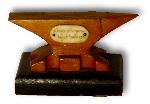
2. WWI Trench Art Anvil
A hand carved wooden anvil made by a prisoner of war in a camp at Amherst, Nova Scotia, Canada.
|
|
- guru
- Saturday, 02/05/11 11:55:43 EST
|
Guru,
If what you've read about the Austro-Hungarians is true (and I have no reason to doubt it), it seems especially ironic. Austria-Hungary wasn't exactly monolithic -- in fact that's what *started* the war. So unless the security folks were more discriminating 100 years ago, I bet a lot of people caught up in those camps were on the allies' side.
|
|
Mike BR
- Saturday, 02/05/11 13:58:33 EST
|
There were POW camps in Kentucky, and they lent out the prisoners to do farm work during WWII. Lots of historical markers attesting to. I have also seen murals of Bavarian scenes in several mess halls left from that era that were painted by homesick POWS. The best as I remember was at Camp Shelby Miss.
As for the broken horn story, I have heard it at several historical sites. I think i have to agree with the guru, that they result from use over many generations.
I suspect that some of the belief may come from the WWII effort to stop German industry by bombing the ball bearing plants putting a road block to building machinery. Easy logic to guess that in the uncivil war the same applied to anvils.
If I had been the General then to want to kill Southern industry, what little they had, I would have blown up the iron furnaces.
|
|
ptree
- Saturday, 02/05/11 14:39:57 EST
|
No different than the Japanese Americans that were imprisoned and their property confiscated during WWII. Many of these folks were voting citizens who's families had been here several generations.
We do the same today lumping anyone of Hispanic descent into the "illegal immigrant" category and all Arabs as terrorists.
|
|
- guru
- Saturday, 02/05/11 14:42:57 EST
|
Thinking about Jeff's carrier story a little more: It seems quite plausible that the Navy understood the fact that it wouldn't be getting any jets if they couldn't fly off carriers better than it understood the laws of physics. . .
|
|
Mike BR
- Saturday, 02/05/11 15:00:48 EST
|
Been sick,
Now pneumatic tires predated WWI but they were rather fragile. Army stuff is generally engineered to NOT be fragile.
Getting early auto's up hills: you didn't mention that the reverse gear was the lowest gear that auto had and so for a steep hill reverse was the way to go!
Gotta remember just cause someone lived back then didn't mean they knew the whole story about things.
Thomas
|
|
Thomas Powers
- Saturday, 02/05/11 15:25:22 EST
|
In the model T, the gas tank was under the front seat, and as Mike T notes it was indeed gravity flow. So climbing a steep hill, especially with a low fuel level required reverse. The early T salesmen were advised to demonstrate that reverse up the hill with a "see, if even climbs a hill in reverse" :)
In WWII, most take offs were non-catapult since they were much faster and safer as a weak shot on the wimpy hydraulic cats would not drop you in the drink.
The Koren war Navy used jets as well as piston engined equipment and the Cat was required for the jets.
Mike Br has it that the Jets accelerated very slowly in the early days due to very low thrust, and no afterburners.
To carry a real load off the deck of the carriers in the early fifties still meant a R-2250 piston engined Douglas AD1. These flew well into the Vietnam era since they hauled a bigger than B-17 load and could loiter far longer than the jets. They were finally retired as the airframes ran out of hours.
Interestly the variable pitch props made the ability to accelerate as Mike Br notes, but even more effective to to slow the prop down by gearing, allowing a bigger prop dioameter. The thrust is a function of prop disc diameter, and area is a square function of the diameter.
So use a huge diameter, slow turning prop and turn all that torque to thrust, instantly. Something a jet can't do. Or use the turbine to turn a gear box and turn a huge prop, think C-130
|
|
ptree
- Saturday, 02/05/11 16:16:50 EST
|
Mistyped, R-2250 should be R-3350. That is a 18 cylinder 3350 cubic inch radial built by Curtiss-Wright. Made about 3200Hp in Standard trim. The "Turbo-Compound" version could make almost 4700Hp from the same displacement with water injection for take-off.(For about 5 minutes)
|
|
ptree
- Saturday, 02/05/11 16:19:40 EST
|
My Dad was a Landing Signal operator during the Korean era, the guy standing on the flight deck with a pair of flags, signaling the pilot on approach. He never talked much about it, but did say they lost some on take-off due to engine power failure or weather problems, but most on landings. Emotionally wracking for the whole crew, but more on him. Launches were supposed to be timed so that the bow was lifted up at the top of a wave. If you watch some of the old videos taken from the deck, you will see that the whole plane drops below the level of the deck at launch. The way a large bird drops from a high perch to get up air speed. Some just don't make it back up in time before the next wave crest arrives.....
|
|
John McPherson
- Saturday, 02/05/11 16:44:21 EST
|
Big props:
Yeah, a huge prop turning slowly can displace a whole lot. Look at the propulsion system on the Aegis class of destroyers. Two 18-foot diameter variable-pitch props only turning about 72 rpm will make that 500+ foot ship practically leap out of the water. I got a brief ride on one some years back and it was throwing a ten-story tall rooster tail as it came out of the hole at full thrust. From dead stop to flank speed in just about its own length and ditto for a full crash stop. That was a real E-ticket ride!
|
|
- Rich
- Saturday, 02/05/11 18:25:22 EST
|
Rich, back in the late 70's I was a co-op student and then once graduated a tester in the engineering labs of Westinghouse Air Brake Co in Lexington KY. One of the projects was the then unheard of constant speed, variable pitch prop for ocean going ships like oil tankers. We were to make the servo positioner, a honking huge servo for those. Bird Johnson was the prime and they demanded accurancy and hystersis beyond the state of the art. I remember measuring hundreds of recirculating ball linear bearings to get nonimal ones in an effort to get the desired performance. I left WABCO before the project closed, so I don't know if they ever got that level.
The slave cylinder was a fairly long stroke 16" bore hydraulic cylinder rated to operate at 5000Psi.
Times sure do change, the then state of the art for throttle brake and gear control on ocean going ships were pnuematic! The controls took 3 each 4' by 8' control enclosures, and were all diaphragm valved!
You can now get that level of control from a PLC about the size of a carton of cigarettes:)
|
|
ptree
- Saturday, 02/05/11 19:51:42 EST
|
Model "T" gas tank: Ford eventually got the right idea, the 1927 "T" had the gas tank in the top of the cowling in front of the dash board, allowing gravity feed up hill with a low tank. We had one of these converted to a farm truck. They were the last of the "T"s.
|
|
- Dave Boyer
- Saturday, 02/05/11 20:33:32 EST
|
Ptree; e-mail to you. was a problem getting thru?
|
|
- bam-bam
- Saturday, 02/05/11 21:47:25 EST
|
Guru; That other vise? Yes it is wrought, and the junk yard dog is chained to it!
Yes I am VERY interested in your Helve drawing.( Don't know if you saw my earlier response.)
|
|
- Keith
- Saturday, 02/05/11 23:53:14 EST
|
Will sketch it up today. . faster than finding the original.
|
|
- guru
- Sunday, 02/06/11 06:31:20 EST
|
Bam-Bam, e-mail received, I was just offline :)
|
|
ptree
- Sunday, 02/06/11 11:05:01 EST
|
Guru; thanks, do you want to send it to me direct?
|
|
- Keith
- Sunday, 02/06/11 15:02:52 EST
|
I have a collection of minature anvils, too, but almost all of mine are euro style, double horned.
Curiously enough, I have the exact anvil that has the naked girl on it- WITHOUT the naked girl.
It has the same text on it, Alcaide, and is the same anvil, from the same pattern.
I guess they just made a PC version, and then the X rated one for special customers.
In argentina, it was common to make small bronze, and sometimes aluminum, anvils with hardware store or metal shops names on them.
|
|
- Ries
- Sunday, 02/06/11 15:38:23 EST
|
Ries, I suspected that Argentinian anvil was distributed separately as yours was. The girl seems to have been soldered on. But I have not examined the actual piece. And you never know. . it may have been a "special" (OR someone might have pried yours off) ;)
I would not call it X rated. Maybe PG-13. . .
While I've found the mini-anvils very interesting, I have never collected them. I have been given two as gifts but I could not tell you where they are. I might have "re-gifted" them.
Keith, I will post them.
|
|
- guru
- Sunday, 02/06/11 16:29:29 EST
|
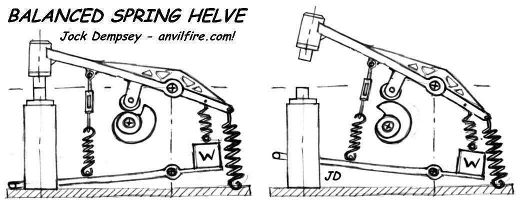
Balanced Spring Helve Hammer
This is an unproven design but it should work. The way it works is that the helve is held off the cam by the balance springs (and or optional weight as shown). When the operator presses down on the treadle it pulls the helve down on the cam and starts it cycling. Press down all the way and the treadle spring cancels the balance springs and pulls the hammer down harder than it would fall by gravity. The force can be feathered in between light and full blows. Connecting one of the balance springs to the weight shown on the treadle reduces some of the counterbalance force when the treadle is pressed. Of course this uses operator force. Nothing is free.
This is a fairly simple design but may require some playing with the springs.
This can also be used with a guided ram such as in the spring helves. Attach it with a short connecting link so that the angle/length change is addressed.
|
|
- guru
- Sunday, 02/06/11 19:04:08 EST
|
Balanced Hammer Detail Notes:
The roller cam could be made of wood or metal, of metal covered wood.
The roller should not hit the low section of the cam. With closed dies there should be a gap between the roller and low section of the cam.
The cam should have a section of about 90 to 180 degrees before starting to lift the helve. 90 would be best.
Maximum operating speed is a little more than 1/2 the acceleration of gravity times the distance. It takes 1/4 second for something to fall 1 foot. A little faster with the springs pulling down. So the cam does not want to rotate faster than 60 RPM if the cam has 90 degrees clear space, 120 RPM with 180 degrees clear space. Yes, falling helves are slow.
If the ram is not guided the helve should have wide bearing spacing. Preferably making the helf an A shaped frame.
|
|
- guru
- Sunday, 02/06/11 20:18:53 EST
|
Guru; looks to me like a worker. Couple questions....the cam itself, what were your thoughts on width, and distance from center of cam hub to the point where follower "drops"?
Next...the distance from helve pivot to hammer and I'm thinking 1/3rd of that for pivot to rear counter-spring.
I have a 1/3 and a 1/2 horse motor and am still trying to locate my motor drive conversion book. Will also check Millwrights/Mechanics Guide.
|
|
- Keith
- Monday, 02/07/11 16:01:35 EST
|
Keith,
I would have to make a scale drawing after selecting some components. I've got some big old 4" OD double row ball bearings I would use for the rollers.
As a gut feeling I would make the cam about 2" wide and the minimum diameter about 6" (150mm) or more. If wood I'd go 10" (250mm).
Speed reduction on the motors is simple ratios. Their nominal speed should be 1800 RPM. Put a 3" pulley on one and got to a 12" pulley on the other and you have 4:1 reduction. 1800/4=450 RPM. So you may need more than one step. For practical purposes 3:1 is the norm but you can get 6:1 with a very large *18" in this example) pulley.
I avoid HP to work calculations and start with torque. A 1HP motor produces 32 inch pounds of torque. Slow it down 8:1 and you get 256 inch pounds or 21.3 foot pounds (minus an inefficiency factor = multiply by 0.9). That means it will lift 20 pounds on a 1 foot lever, or 40 pounds on a 6".
IF your motors spec plate operating RPM's are the same then you can couple the two motors together for 0.8 (a little more than 3/4) HP.
The helve lever gives the hammer/ram a mechanical advantage. With the cam roller at 1/3 a 40# hammer will require 120 pounds to lift it. The ram (wedge) of the cam does the opposite increasing the lift. This should just about cancel out the lever ratios (I think). I would use the calculated torque at the minimum cam radius.
There are some practical limits to this design. A portion of the balance springs must be overcome by the force applied on the treadle by your foot. As the machine becomes larger this force becomes greater and control less.
|
|
- guru
- Monday, 02/07/11 17:45:27 EST
|
ptree- there were POW's held at the AVON Signal Corp. Depot during WW2. One of my school teachers talked about them working on her fathers farm.
One of my running buddies worked at WABCO during the late 70's, until they closed or laid him off. I forget which now.
|
|
- Brian C.
- Monday, 02/07/11 18:54:12 EST
|
Brian C. WABCO Fluid Power division in Lexington KY was sold and became a division of Mannesman RexRoth in the '80s I think. Nice place to work and learn, especially in the engineering labs. The plant is still open.
I have seen historical markers in a number of central KY locations detailing POW facts.
|
|
ptree
- Monday, 02/07/11 19:00:05 EST
|
I have a chance to pick up a Kerrihard power hammer
#20 Can you tell me if it is a good one for small stuff. Also any idea on the value? It looks in good condition. Thanks
|
|
Harold G
- Monday, 02/07/11 20:07:48 EST
|
Guru,
How can I determine the suitable etching method for chrome steel, if I would like to see their grain structure under microscope?
|
|
- fatbamboo
- Monday, 02/07/11 23:38:07 EST
|
I think nital is the etchant most often used in metallography.
|
|
- Ty Murch
- Monday, 02/07/11 23:42:23 EST
|
Kerihard Hammers: Harold, these are a fairly complicated hammer with a lot of working and wearing parts. They are also an orphan machine. That means that if anything goes wrong you have to figure it and make or design and have someone else make replacement parts. These hammers have been selling for around $1000 to $1500. But they may go fro more if in perfect condition and less if not so perfect.
|
|
- guru
- Monday, 02/07/11 23:49:17 EST
|
I think that the finish, the polish put on the steel is probably as important or more important than the etch. When we were machining large pieces of stainless steel the crystal structure was obviously visible to the naked eye without etching due to the fine finish.
|
|
- guru
- Monday, 02/07/11 23:51:43 EST
|
Fatbamboo, there are a number of etchants used to study microsturcture. The Guru notes that surface condition is important and he is very correct. To see microstructure it is normal to cut with a saw, and then sand the surface down to a very fine polish using finer and finer grits. At least 400 grit but often down to 1000 grit or finer.
Note! most etchants are unstable if mixed too strong. Nital etchant, the most commonly used is a mixture of methanol alcohol and Nitric acid. Mived volume by volume at 5% nitric to 95% alcohol it works well. Mixed to a stronger acid content, it is unstable, and generates both heat and gas. Mixed above 19% if I recall correctly, it makes unstable peroxides and will often explode the bottle!
search the net for metal etchants and you will find several references for different etchants and the safety practices for each.
|
|
ptree
- Tuesday, 02/08/11 07:29:24 EST
|
Ptree, does PC board etchant work for this purpose?
|
|
- guru
- Tuesday, 02/08/11 07:42:45 EST
|
Yes, printed circuit etchant, ferric chloride, will work in a dilute solution, but it is not the preferred etchant for metallography as it has a tendency to create more oxides. The same reason it is desirable for showing the contrast in pattern-welded steel makes it less desirable for fine detail in metallography studies, from what I understand.
|
|
- Rich
- Tuesday, 02/08/11 08:35:26 EST
|
I have not heard og PC board etchant being used for metallography. Most folks are doing the etching to support quality control and follow the ASTM standard. In that standard are a number of etchants.
Nital is actually one of the friendlier, Picral used to be quite popular, but must be keep wet with at least 30% pure water. The dry crystals are shock and friction sensative and unscrewing the lid or twisting the stopper from a "dry" jar of Picral (picric acid) can be exciting!
Ptree who has done the emergency response and clean-up from several Nital etchant explosions from too much acid in the mix :)
|
|
ptree
- Tuesday, 02/08/11 10:20:01 EST
|
|
|
[
Getting Started in Blacksmithing ]
|