|
|
|
On the Construction of Locks and Keys by John Chubb
|
CONSTRUCTION OF LOCKS AND KEYS. 11
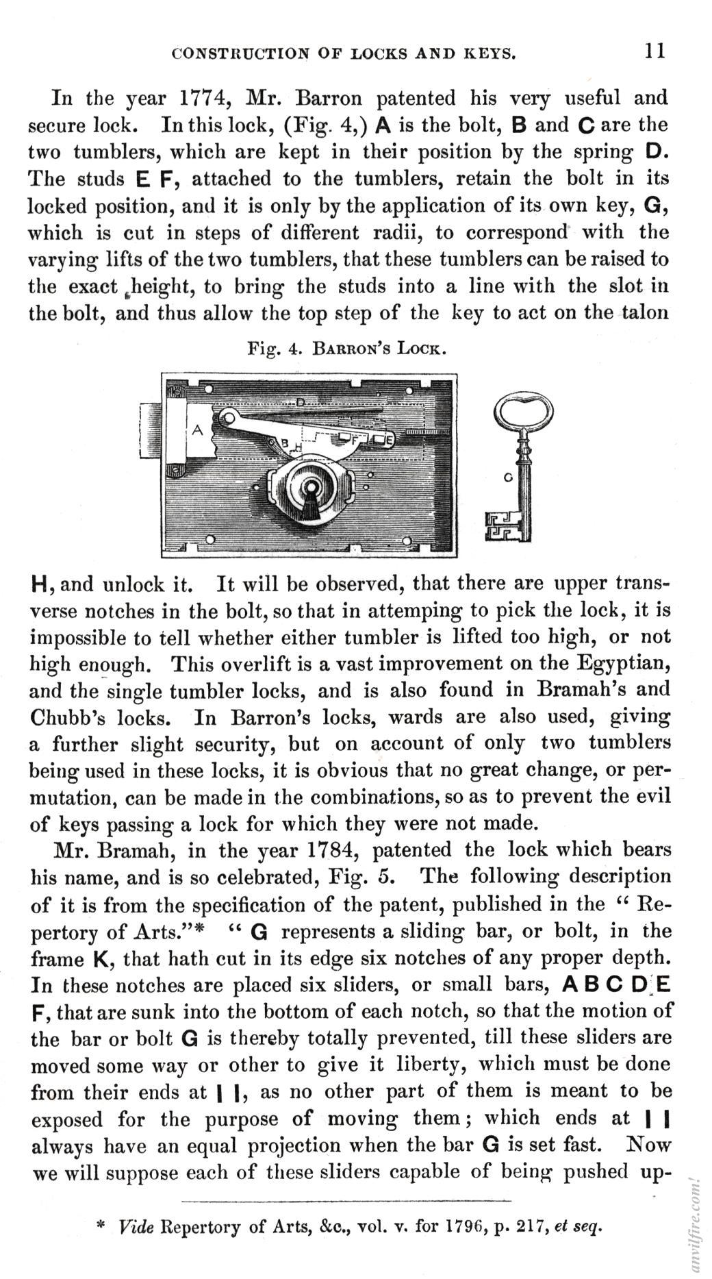
In the year 1774, Mr. Barren patented his very useful and secure lock. In this lock, (Fig. 4,) A is the bolt, B and C are the two tumblers, which are kept in their position by the spring D. The studs E F, attached to the tumblers, retain the bolt in its locked position, and it is only by the application of its own key, G, which is cut in steps of different radii, to correspond with the varying lifts of the two tumblers, that these tumblers can be raised to the exact Jieight, to bring the studs into a line with the slot in the bolt, and thus allow the top step of the key to act on the talon
Fig. 4. BARRON'S LOCK.
H, and unlock it. It will be observed, that there are upper transverse notches in the bolt, so that in attemping to pick the lock, it is impossible to tell whether either tumbler is lifted too high, or not high enough. This overlift is a vast improvement on the Egyptian, and the single tumbler locks, and is also found in Bramah's and Chubb's locks. In Barren's locks, wards are also used, giving a further slight security, but on account of only two tumblers being used in these locks, it is obvious that no great change, or permutation, can be made in the combinations, so as to prevent the evil of keys passing a lock for which they were not made.
Mr. Bramah, in the year 1784, patented the lock which bears his name, and is so celebrated, Fig. 5. The following description of it is from the specification of the patent, published in the " Repertory of Arts."* " G represents a sliding bar, or bolt, in the frame K, that hath cut in its edge six notches of any proper depth. In these notches are placed six sliders, or small bars, A B C D E F, that are sunk into the bottom of each notch, so that the motion of the bar or bolt G is thereby totally prevented, till these sliders are moved some way or other to give it liberty, which must be done from their ends at | |, as no other part of them is meant to be exposed for the purpose of moving them; which ends at | | always have an equal projection when the bar G is set fast. Now we will suppose each of these sliders capable of being pushed up-
* Vide Repertory of Arts, &c., vol. v. for 1796, p. 217, et seq.
|
|
|

On the Construction of Locks and Keys by John Chubb