Building a machine, even a
Junk Yard Hammer requires some machinery.
At a minimum a cutting torch and an arc welder.
But hole drilling is a big part of building maintainable machinery so a good metal working drill press is highly recommended.
You don't need all the machines below but you need access to them OR pay someone to do the work.
We paid for all the large stock to be cut to size.
This included sawing the structurals and the anvil material.
We also paid a machine shop $30 to broach several keyways.
We had access to a
milling machine to machine the guide inserts but could have paid someone else.
One option to paying for the machine work is to take a machine shop course.
There is often time OR a need for personal projects.
If you have detailed drawings such as from purchased plans you may be able to get classmates to help.
Be up front with your instructor, they are usually glad to be of help.
The following is a list of tools and machines used to build the X1 hammers.
Machines
- 4 x 6" Cutoff Saw A good one that cuts square (Ridgid)
- 20 to 25" Back Geared HD Drill Press (Champion 25")
- 6" Engine Lathe Craftsman 1950
- 16" Engine Lathe Southbend 1930
- Milling Machine SEIKI XL (Bridgport Clone)
- Oxy-Acetylene Cutting Torch
- Arc Welder Miller Thunderbolt 225 AC
- Arbor Press (for broaching keyways)
- Bench Grinder
- Magnetic Based Drill Press (Optional)
- Air Compressor To power die grinder, blow out holes.
- Lifting Means Hoist, Crane or Forklift
Machine tools require a minimum of standard attachements, chucks, centers, vices. . .
Hand Tools & Accessories
- 6" Dial Caliper
- 8" Dividers
- 12" Machinest's Square
- Drill Bits from number sizes to 1.5"
- Taps for holes 10-32, 1/4-28, 7/16-20, 1/2-13, 1/2-20, 9/16-18, 3/4-16
- Angle Grinder(s)
- Die Grinder air or electric
- 1.375 or 1.500 Adjustable Reamer For pitman
- .875 and .501 Reamer For motor pulley and toggles
- C-Clamps, pipe clamps, bar clamps Never enough. . .
- Tapping Head Tapmatic - Used with drill press to speed up tapping.
The lists above do not include standard hand and mechanics tools neccessary to run or maintain the machines, or assemble the power hammer.
A large steel welding bench or weld platten is also highly recommended. But I have built large projects on the bare ground. . .
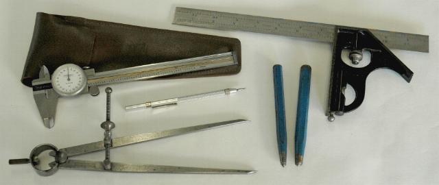
The measuring and layout tools above are the minimum but more than sufficient for this job.
Good accurate 6" (150mm) dial calipers do for most measuring where micrometers are often used and are easier to read.
The calipers have the range needed for all the layout tasks requiring fine measurements.
A square is also needed. Those like the Starrett above with satin chromed scales are the easiest to read thus avoiding errors.
But a carpenter's square is also handy.
Good dividers with hard sharp points are an absolute requirement unless you have a shop full of machinery with digital readouts.
The carbide scriber more than pays for itself on a job like this.
Drilling Holes
The experianced machinist knows holes can be made with numerous machine tools.
The choice of which to use depends on capacity, availability and efficiency.
In general holes are made the fastest on a good drill press but can also be drilled on milling machines with a quill (such as a Bridgeport).
But holes can also be drilled and bored on a lathe. For some fits this is the best method.
Holes in structurals are best made with a magnetic based drill press but can also be made on a drill press or mill IF the work can be brought to and supported on those machines.
Even a hand crank blacksmiths drill could be used to make many of the holes on a project like this.
Taping Holes
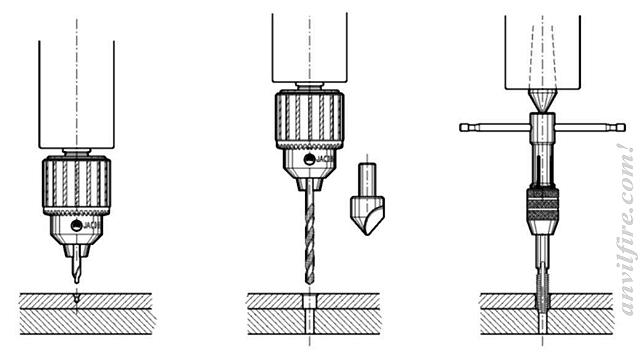
Most of the holes were taped in place by hand on the drill press(s) as they were drilled. The sequence goes like this.
- Install Point in chuck.
- Align drill chuck to center punch mark using point in chuck.
- Install Tap Drill in chuck.
- Tap drill through both parts of assembly.
- Install nominal size drill in chuck.
- Drill on-size hole through un-threaded part.
- Install Point in chuck or center in spindle.
- Tap using center in drill press to align tap.
- Install clearance drill in chuck.
- Clearance drill un-threaded part
- Continue to next hole
- When complete, seperate parts and chamfer all holes, run tap through again to clean up.
Using this technique one hole at a time assures good results and avoids breaking taps.
Be sure to use a good tap lube such as Tap Free or Magic Tap.
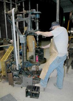
The 24 guide adjustment screw holes were taped with a taping head (image at right). The sequence for this is.
- Align tap drill to center punch mark.
- Tap drill through.
- Continue for all holes.
- Float work to chamfer all holes.
- Install Tapping Head and reaction bar.
- Float work to align.
- Power tap hole.
- Continue to next hole.
There are far fewer tool changes using the taping head if you have one.
This makes the job go faster but it is an optional tool.
You don't buy one for a small job like this.
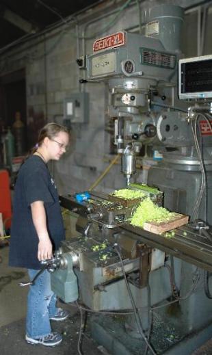
 Sandy Wilson Milling Guide Inserts
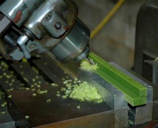
Above, Milling corner relief with ball end mill.
The only milling job on the X1 project was making the plastic guide inserts.
It took about 6 hours while training a novice machinist to make 9 inserts (8 plus an extra).
An expert machinist should be able to make 4 in about 3 hours or less.
The oil filled Nylon machines like butter with a good sharp cutter and is easy to achieve the required dimensions.
There were other jobs where a milling machine COULD have been used but were unnecessary on this project.
If you make your own dies or die holders a mill (or shaper) is required for them as well.
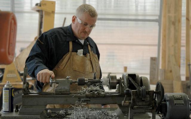 Dave drilling on Craftsman Lathe
The bulk of our machining was done on an old worn 6" Craftsman Engine Lathe.
The crank, crank washer, pitman head, pitman screw, motor pulley, treadle adjustment block were machined on this lathe.
Lock nuts were faced and the spring bolt modification made.
The only turning job requiring a larger lathe was facing the crank shaft flange after welding.
Our drilled fit was not tight enough and the welding pulled the flange crooked to the shaft.
This was machined on a larger 16" South Bend lathe (which could have been used for the entire job).
In many of these tasks the cutoff saw and the drill press were supporting machines.
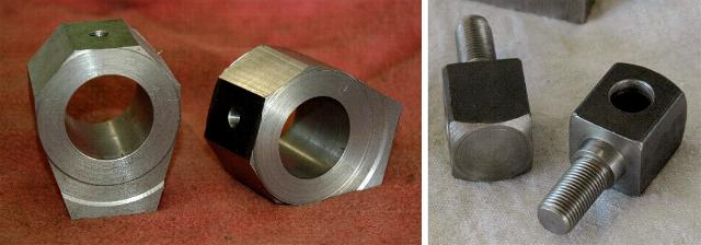
The pitman heads (above left) were faced and bored on the lathe while rectantular, corners sawed off on the cutoff saw (as shown), then hand sculpted to shape with a 4-1/2" angle grinder and files.
Later the acme screws were welded on, the bronze bushings pressed in and then reamed to size.
The treadle connector blocks were machined on the lathe then drilled and threaded on the drill press.
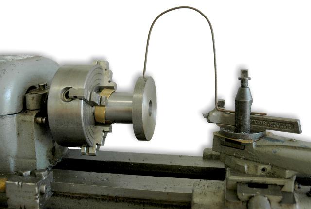
Working without a dial indicator.
I have a drawer full of expensive dial indicators and holders including little Starrett Last Word sets that are perfect for use on this small lathe.
However, on this project I was teaching someone how to use a lathe and how this task could be done without a fancy dial indicator.
The bent piece of 1/16" welding rod has a point ground on it and then was adjusted to just touch the work.
The work was adjusted in the four jaw chuck until the the same narrow band of light could be seen between the point and the work then wire just barely touching all the way around as the work was rotated.
The accuracy of centering the work was well within the tolerance needed (+/-0.001") to face and relieve the back of the crank pin.
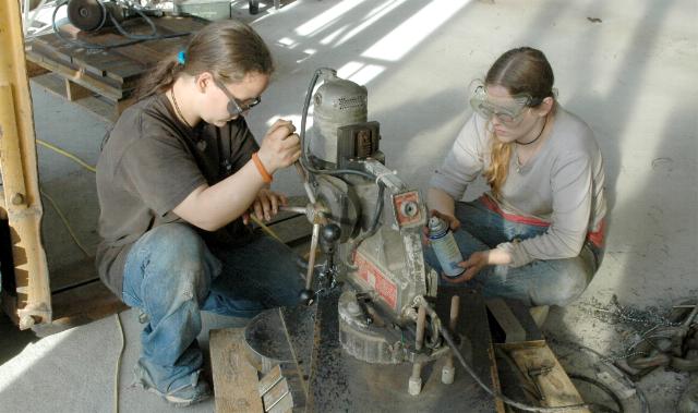
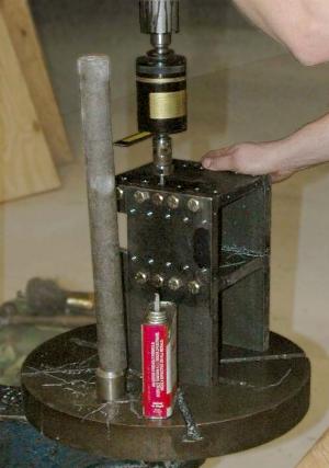
Sandy and Becka Drilling Holes in Base Plate.
The Magnetic Based Drill Press was only used once on this project and was not necessary.
However, it was more convienient to carry the 98 pound drill press to the base plate than to wrangle the 102 pound plate on the drill press repositioning it for every hole.
We could have drilled to the center of the plate on the big Champion but it was busy at the time.
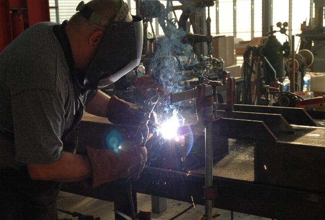
Welding the Frame
All the welding on this project was done with an old Miller AC buzz box.
The frame pass through complicated the frame a bit adding to the need for more clamps and a big flat welding bench.
The pass through was made from a 12" section of the 12 x 6" frame material thus did not require more of this expensive structural tube.
IF angled bolt on dies are used the pass through could be left off this hammer making the frame easier to construct.
NEXT Page Drawings and Plans
Links:


One option to paying for the machine work is to take a machine shop course. There is often time OR a need for personal projects. If you have detailed drawings such as from purchased plans you may be able to get classmates to help. Be up front with your instructor, they are usually glad to be of help.
The following is a list of tools and machines used to build the X1 hammers.
Machines
- 4 x 6" Cutoff Saw A good one that cuts square (Ridgid)
- 20 to 25" Back Geared HD Drill Press (Champion 25")
- 6" Engine Lathe Craftsman 1950
- 16" Engine Lathe Southbend 1930
- Milling Machine SEIKI XL (Bridgport Clone)
- Oxy-Acetylene Cutting Torch
- Arc Welder Miller Thunderbolt 225 AC
- Arbor Press (for broaching keyways)
- Bench Grinder
- Magnetic Based Drill Press (Optional)
- Air Compressor To power die grinder, blow out holes.
- Lifting Means Hoist, Crane or Forklift
Machine tools require a minimum of standard attachements, chucks, centers, vices. . .Hand Tools & Accessories
- 6" Dial Caliper
- 8" Dividers
- 12" Machinest's Square
- Drill Bits from number sizes to 1.5"
- Taps for holes 10-32, 1/4-28, 7/16-20, 1/2-13, 1/2-20, 9/16-18, 3/4-16
- Angle Grinder(s)
- Die Grinder air or electric
- 1.375 or 1.500 Adjustable Reamer For pitman
- .875 and .501 Reamer For motor pulley and toggles
- C-Clamps, pipe clamps, bar clamps Never enough. . .
- Tapping Head Tapmatic - Used with drill press to speed up tapping.
The lists above do not include standard hand and mechanics tools neccessary to run or maintain the machines, or assemble the power hammer. A large steel welding bench or weld platten is also highly recommended. But I have built large projects on the bare ground. . .The measuring and layout tools above are the minimum but more than sufficient for this job. Good accurate 6" (150mm) dial calipers do for most measuring where micrometers are often used and are easier to read. The calipers have the range needed for all the layout tasks requiring fine measurements. A square is also needed. Those like the Starrett above with satin chromed scales are the easiest to read thus avoiding errors. But a carpenter's square is also handy. Good dividers with hard sharp points are an absolute requirement unless you have a shop full of machinery with digital readouts. The carbide scriber more than pays for itself on a job like this.
Drilling Holes
The experianced machinist knows holes can be made with numerous machine tools. The choice of which to use depends on capacity, availability and efficiency. In general holes are made the fastest on a good drill press but can also be drilled on milling machines with a quill (such as a Bridgeport). But holes can also be drilled and bored on a lathe. For some fits this is the best method. Holes in structurals are best made with a magnetic based drill press but can also be made on a drill press or mill IF the work can be brought to and supported on those machines. Even a hand crank blacksmiths drill could be used to make many of the holes on a project like this.Taping Holes
Most of the holes were taped in place by hand on the drill press(s) as they were drilled. The sequence goes like this.The 24 guide adjustment screw holes were taped with a taping head (image at right). The sequence for this is.
- Align tap drill to center punch mark.
- Tap drill through.
- Continue for all holes.
- Float work to chamfer all holes.
- Install Tapping Head and reaction bar.
- Float work to align.
- Power tap hole.
- Continue to next hole.
There are far fewer tool changes using the taping head if you have one. This makes the job go faster but it is an optional tool. You don't buy one for a small job like this.Above, Milling corner relief with ball end mill.
The only milling job on the X1 project was making the plastic guide inserts. It took about 6 hours while training a novice machinist to make 9 inserts (8 plus an extra). An expert machinist should be able to make 4 in about 3 hours or less.
The oil filled Nylon machines like butter with a good sharp cutter and is easy to achieve the required dimensions.
There were other jobs where a milling machine COULD have been used but were unnecessary on this project. If you make your own dies or die holders a mill (or shaper) is required for them as well.
 Dave drilling on Craftsman Lathe
The bulk of our machining was done on an old worn 6" Craftsman Engine Lathe. The crank, crank washer, pitman head, pitman screw, motor pulley, treadle adjustment block were machined on this lathe. Lock nuts were faced and the spring bolt modification made. The only turning job requiring a larger lathe was facing the crank shaft flange after welding. Our drilled fit was not tight enough and the welding pulled the flange crooked to the shaft. This was machined on a larger 16" South Bend lathe (which could have been used for the entire job).
In many of these tasks the cutoff saw and the drill press were supporting machines.
The pitman heads (above left) were faced and bored on the lathe while rectantular, corners sawed off on the cutoff saw (as shown), then hand sculpted to shape with a 4-1/2" angle grinder and files. Later the acme screws were welded on, the bronze bushings pressed in and then reamed to size. The treadle connector blocks were machined on the lathe then drilled and threaded on the drill press.
Working without a dial indicator.
I have a drawer full of expensive dial indicators and holders including little Starrett Last Word sets that are perfect for use on this small lathe. However, on this project I was teaching someone how to use a lathe and how this task could be done without a fancy dial indicator.
The bent piece of 1/16" welding rod has a point ground on it and then was adjusted to just touch the work. The work was adjusted in the four jaw chuck until the the same narrow band of light could be seen between the point and the work then wire just barely touching all the way around as the work was rotated. The accuracy of centering the work was well within the tolerance needed (+/-0.001") to face and relieve the back of the crank pin.
The Magnetic Based Drill Press was only used once on this project and was not necessary. However, it was more convienient to carry the 98 pound drill press to the base plate than to wrangle the 102 pound plate on the drill press repositioning it for every hole. We could have drilled to the center of the plate on the big Champion but it was busy at the time.
Welding the Frame
All the welding on this project was done with an old Miller AC buzz box. The frame pass through complicated the frame a bit adding to the need for more clamps and a big flat welding bench. The pass through was made from a 12" section of the 12 x 6" frame material thus did not require more of this expensive structural tube. IF angled bolt on dies are used the pass through could be left off this hammer making the frame easier to construct.
NEXT Page Drawings and Plans
Links: