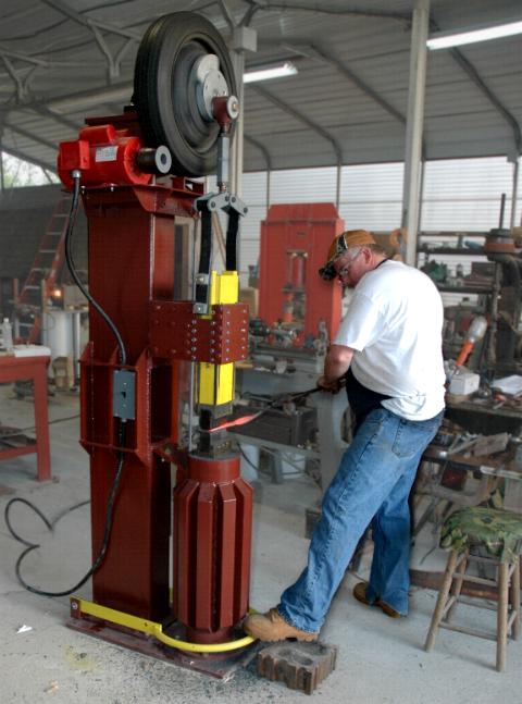
A mechanical power hammer treadle needs to be relatively stiff or it will twist when pressing on it from the oposite side of the connecting link.
To be ridgid in three dimensions the treadle needs to be either heavy bar or hollow structural.
For this purpose pipe works best.
We used 1" Schedule 40 pipe (1.315" OD) for the contact area and 3/8" x 2 flat bar for the arms.
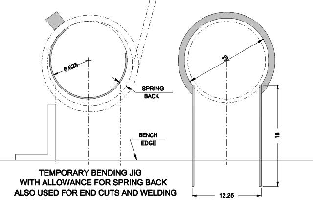
Pipe can be rolled, bent on a Hossfeld Bender, bent with a manual or hydraulic conduit bender or using a purpose made jig.
We used a special jig rolled on a tire bender and tack welded temporarily to our welding bench.
This was using what we had available at the moment and fairly efficient since we were making two treadles at the same time.
The scrolling wrench was used on the jig, not the pipe.
The pipe was bent using the extra for leverage, no tools needed.
The bend was completed as far as it could go then adjusted on an arbor press to the correct diameter (we did not allow for spring back as above).
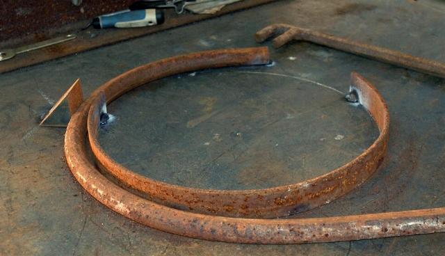
After bending, cut lines were drawn using chalk and then sawed.
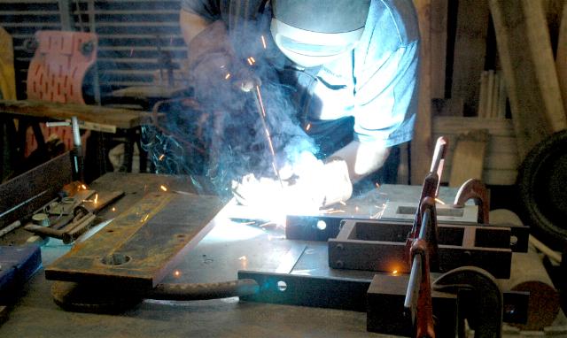 The chalk layout of the treadle was completed after bending and used to setup the parts for welding.
Making two treadles was a good afternoon's work.
The chalk layout of the treadle was completed after bending and used to setup the parts for welding.
Making two treadles was a good afternoon's work.
Making the treadle connecting rod and adjustment block.
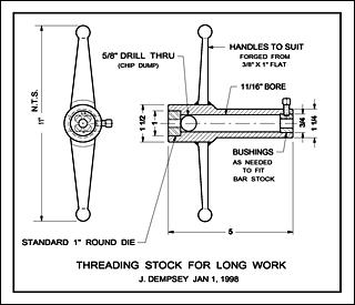 My Long Threading Stock was made for a job back in the 1970's and has come in handy a number of times.
I wrote an article about it in 1989 for
The Blacksmith's Gazette.
My Long Threading Stock was made for a job back in the 1970's and has come in handy a number of times.
I wrote an article about it in 1989 for
The Blacksmith's Gazette.
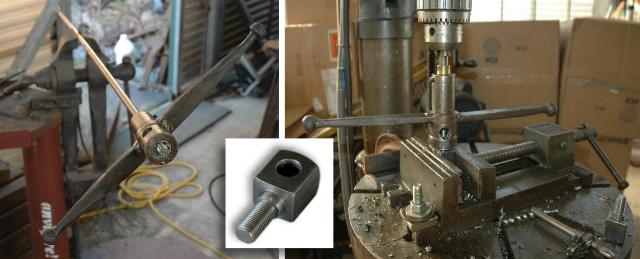
The advantage of this tool is it has a long body and a guide bushing at the far end.
To thread a piece of rod you just cram it on and start cranking.
It will easily make a long straight thread unlike conventional die stocks which are hard to start and difficult to keep straight.
On the drill press I reversed the start end of the die and used it udside down.
A short piece of round bar stock was clamped in the chuck as a guide.
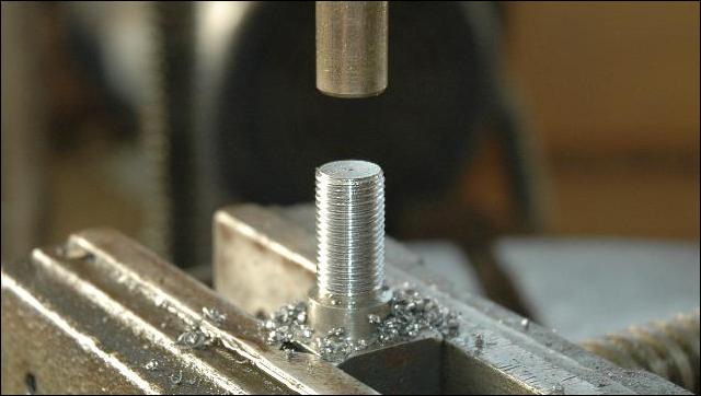 Guide pin and perfectly threaded part.
A similar arrangement can be used on the drill press using a conventional die stock if it has adjustable guides (many have no guides at all).
This can also be done on the lathe.
Guide pin and perfectly threaded part.
A similar arrangement can be used on the drill press using a conventional die stock if it has adjustable guides (many have no guides at all).
This can also be done on the lathe.


Pipe can be rolled, bent on a Hossfeld Bender, bent with a manual or hydraulic conduit bender or using a purpose made jig. We used a special jig rolled on a tire bender and tack welded temporarily to our welding bench. This was using what we had available at the moment and fairly efficient since we were making two treadles at the same time.

The scrolling wrench was used on the jig, not the pipe. The pipe was bent using the extra for leverage, no tools needed. The bend was completed as far as it could go then adjusted on an arbor press to the correct diameter (we did not allow for spring back as above). After bending, cut lines were drawn using chalk and then sawed.
The advantage of this tool is it has a long body and a guide bushing at the far end. To thread a piece of rod you just cram it on and start cranking. It will easily make a long straight thread unlike conventional die stocks which are hard to start and difficult to keep straight.
On the drill press I reversed the start end of the die and used it udside down. A short piece of round bar stock was clamped in the chuck as a guide.
 Guide pin and perfectly threaded part.
A similar arrangement can be used on the drill press using a conventional die stock if it has adjustable guides (many have no guides at all).
This can also be done on the lathe.
Guide pin and perfectly threaded part.
A similar arrangement can be used on the drill press using a conventional die stock if it has adjustable guides (many have no guides at all).
This can also be done on the lathe.