Knowledge of how many machines work is a junk builders most important tool.
Some mechanisms are relatively rare and few get a change to study them.
This is the case of the power hammer linkage.
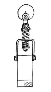
FIRST I want to point out that our EC-JYH shock absorber linkage at left is NOT a good hammer construction method.
Shocks are designed to absorb energy, not return it or delivery energy.
But this was an idea we had for MANY years and had to try it.
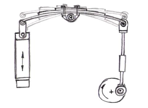
This linkage starts with a heavy blow and then hits lighter as it goes faster.
This is counter intuitive and makes the hammer very inefficient.
As it runs faster it finally stops striking the work at all the ram just floating above the work. . .
While this seems very strange it is EXACTLY what you want auto suspension to do.
Support the load without transferring the motion of bouncing tires to the body.
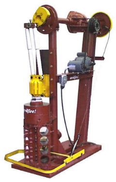
On the other hand, it did work well enough to forge steel.
This machine also demonstrated some other ideas that had been in our minds for decades.
The auto differential as clutch. Using multiple motors on the same drive train.
Multiple Motors: I had many long discussions with various engineers who said multiple motors would not work.
They said that one would take the load and if slowed enough the other would supply some energy causing the first to speed up and the system increase and decrease in speed constantly.
This is known as "hunting" and DOES occur in some mechanisms - but not here. In actuality the two motors work like two weights on a rope.
Each adds its own weight, or in the case of a motor its torque.
The only rules you have to follow is that BOTH motors have the same full load speed rating and both have the same pulleys.
You can put two motors on one belt as I did on the EC-JYH, OR use more than one belt going to a multi-V pulley.
DuPont Type Linkages
Note that what is shown below is only the work height compensation and stroke increasing linkage.
All these machines require a clutch mechanism and most of the machines mentioned also had crank stroke and work height adjustments.
 DuPont Fairbanks
This is the original DuPont linkage.
Little Giant got around the DuPont patent by using T-toggles without pins on their early hammers.
When the DuPont patent expired Little Giant converted to toggle arms with pins.
The popular DIY Tire Hammer uses this linkage.
The toggle arms produce infinite leverage when at a straight line.
This leverage decreases as the angle increases.
This gives the spring the mechanical advantage to stop the ram but it applies no resistance as the ram move through the 0 angle position just before it strikes the work.
This is what gives the DuPont type linkages their so called "snap" or hard high velocity blow.
All the DuPont style linkages shown store the upward momentum of the ram in a spring or elastomer and return that energy on the down stroke.
This also increases the stroke of the hammer as much as two times the crank travel.
 DuPont : Little Giant
IF run too fast for the spring tension this linkage fails in a mode known as the "Little Giant Hula".
Everything moves except the ram floats or is going up when its supposed to go down and down when its supposed to go up.
Before it gets this bad it often skips beats then hits hard and then soft.
This is known as the "Bang Tap Blues" , the title of the
video By Dave Manzer explaining how to tune Little Giants.
I believe this problem is related to the longer toggle links used by LG as the problem seems to be less common on hammers with shorter links such as the Fairbanks.
Most DIY designs get around these problems by running slow with relatively light rams.
On late Little Giants (left) they reversed the pitman and put the work height adjustment above the crank rather than below it.
They used the same parts as on earlier hammers but shortened the frame several inches saving on iron in the process.
The trade off is more horizontal motion of the the heavy toggle arms and springs.
DuPont : Bradley Compact
Bradley got around the DuPont patent by not using a coil spring.
They used rubber "springs" similar to the snubbers they had used on their helve hammers for decades.
Other makers used a similar arrangement with dual coil springs where the rubber blocks are.
No matter what type of spring is used the toggles produce the same variable leverage geometry and increase in stroke.
The tension adjustment on this arrangement is cleaner than on the Little Giant but requires two springs rather than one.
The leverage of the arms is much greater as shown. This is needed due to the stiffness and low motion of the rubber springs.
If coil springs were used less leverage would be needed.
 DuPont : Champion Bow Spring
Many makers used this style bow spring arrangement.
Most had leather straps in place of the toggles but these give a similar action when applied against springs.
Straps provided a method of tensioning the spring by adjusting their length.
As shown the springs must be properly arced for the preload and there is no adjustment.
Some makers have used multiple holes in the toggle links but these produce large changes in tension.
A turnbuckle type toggle link can be used but is a complicated part requiring a yoke on one end and left and right hand screws as well as a locking mechanism.
They also need considerable length as the adjustment range is a small part of the length.
Two advantages of this arrangement is the reduction of pivot points and the replacement of the link arms with the springs.
See: Bow Spring Linkage From the CR-JYH article for more details.
Reverse Bow Spring
There are drawings of the Kerrihard with the spring on the ram but it is not known if any were built.
If pre-tensioning is not sufficient, this would either require a turnbuckle toggle adjustment OR spring stiffener arrangement.
The advantage of this arrangement is it reduces non-working reciprocal weight adding it to the ram.
Combined with replacing the link arms with the springs this is a very efficient mechanical arrangement.
Dempsey Quarter Elliptic
Similar to the reverse bowspring this arrangement can be adjusted with shim plates or pivots and screws as on the anvilfire X1 power hammer.
This has the advantages of the DuPont linkage without the disadvantage of all that hard to balance inefficient reciprocal mass typical on Little Giants and other hammers.
The "quarter elliptic" spring is a common leaf spring cut in half.
These half springs were used on various British cars including 1950's Austins.
Dempsey Rubber Band
This is an untested, unproven design requiring a heavy elastomer "spring".
It has two rigid "ram horns" with a heavy rubber band or elastomer stretched between.
This could be heavy natural rubber or a nylon rope.
Much testing would be required and heating of the elastomer would probably be an issue as it was on the largest Bradley hammer with a leather strap ram linkage.
This is similar to the old leather belting straps that linked to the ram on many hammers except that this puts the arms on the ram for more efficient use of mass and uses a stretchy connecting material.
In this design the elastomers are the toggle links, pivots and springs. This is an absolute minimalist arrangement.
Dempsey Ram Coil
This is similar to the above but uses 4 tension springs (a pair on each side) in place of the rubber bands.
This is another untested unproven design but would surely work on a light hammer.
Tensioning would need to be guessed at (8 to 10 x the ram weight) and the preload performed when bolting on the arms or an adjustment system used where the arms attach to the ram.
Due to the rotation at the ends the springs should ride on bronze bushings to reduce wear.
This is not quite as minimalist as the rubber band but is very close.
Pogo Stick (non-DuPont)
This is a design that comes up repeatedly and has been built by a number of people.
It is more complicated to build than shown and has few merits other than it WILL work in a limited manner.
However, the springs need to be quite stiff and there is less "snap" than in DuPont style linkages.
In general this is an energy wasting linkage that trys to lift the machine off the ground with every stroke.
Unless the springs are balanced exactly for the mass of the ram and speed of the machine no usable work can be gotten from it.
Spring Helve or Feather Hammer
The spring helve was a popular design in Europe for commercial and DIY blacksmiths hammers and has only recently become popular in the US due to the plans for the Appalachian "Rusty" series.
There are numerous variations but the geometry is always the same with the exception of the ram link shown.
Springs are most often straight or slightly bowed and have extra leaves on both top and bottom.
Couplings vary most often clamping to the springs and the front of many hammers simply have the leaf spring going through a slot in the ram.
Sometimes this has roller bearings but most often not.
The advantage of this arrangement is that it results in a short machine.
The disadvantage is that it has a large footprint compared to vertically configured hammers.

This helve design keeps the helve raised and off the cam until the operator presses on the treadle.
This is another untested design.
Ideally as the operator presses farther the harder the hammer strikes.
There are many other power hammer linkages but the DuPont and its variations have been the most successful followed by the spring helve.
While Bradley and a few others made many helve hammers the dynamics of the snubbing systems were complicated and difficult to make work properly.


FIRST I want to point out that our EC-JYH shock absorber linkage at left is NOT a good hammer construction method. Shocks are designed to absorb energy, not return it or delivery energy. But this was an idea we had for MANY years and had to try it.
This linkage starts with a heavy blow and then hits lighter as it goes faster. This is counter intuitive and makes the hammer very inefficient. As it runs faster it finally stops striking the work at all the ram just floating above the work. . . While this seems very strange it is EXACTLY what you want auto suspension to do. Support the load without transferring the motion of bouncing tires to the body.
On the other hand, it did work well enough to forge steel.
This machine also demonstrated some other ideas that had been in our minds for decades. The auto differential as clutch. Using multiple motors on the same drive train.
Multiple Motors: I had many long discussions with various engineers who said multiple motors would not work. They said that one would take the load and if slowed enough the other would supply some energy causing the first to speed up and the system increase and decrease in speed constantly. This is known as "hunting" and DOES occur in some mechanisms - but not here. In actuality the two motors work like two weights on a rope. Each adds its own weight, or in the case of a motor its torque. The only rules you have to follow is that BOTH motors have the same full load speed rating and both have the same pulleys. You can put two motors on one belt as I did on the EC-JYH, OR use more than one belt going to a multi-V pulley.
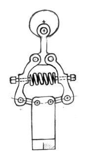
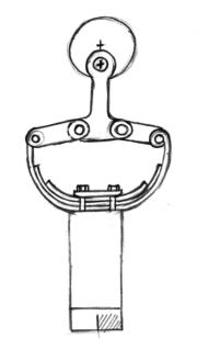
DuPont Type Linkages
Note that what is shown below is only the work height compensation and stroke increasing linkage. All these machines require a clutch mechanism and most of the machines mentioned also had crank stroke and work height adjustments.This is the original DuPont linkage. Little Giant got around the DuPont patent by using T-toggles without pins on their early hammers. When the DuPont patent expired Little Giant converted to toggle arms with pins. The popular DIY Tire Hammer uses this linkage.
The toggle arms produce infinite leverage when at a straight line. This leverage decreases as the angle increases. This gives the spring the mechanical advantage to stop the ram but it applies no resistance as the ram move through the 0 angle position just before it strikes the work. This is what gives the DuPont type linkages their so called "snap" or hard high velocity blow.
All the DuPont style linkages shown store the upward momentum of the ram in a spring or elastomer and return that energy on the down stroke. This also increases the stroke of the hammer as much as two times the crank travel.
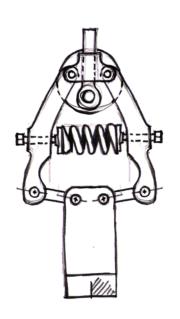
IF run too fast for the spring tension this linkage fails in a mode known as the "Little Giant Hula". Everything moves except the ram floats or is going up when its supposed to go down and down when its supposed to go up. Before it gets this bad it often skips beats then hits hard and then soft. This is known as the "Bang Tap Blues" , the title of the video By Dave Manzer explaining how to tune Little Giants. I believe this problem is related to the longer toggle links used by LG as the problem seems to be less common on hammers with shorter links such as the Fairbanks.
Most DIY designs get around these problems by running slow with relatively light rams.
On late Little Giants (left) they reversed the pitman and put the work height adjustment above the crank rather than below it. They used the same parts as on earlier hammers but shortened the frame several inches saving on iron in the process. The trade off is more horizontal motion of the the heavy toggle arms and springs.

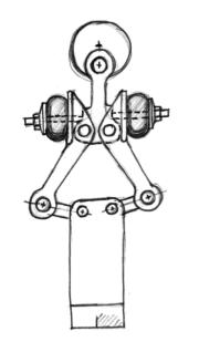
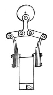
DuPont : Bradley Compact
Bradley got around the DuPont patent by not using a coil spring. They used rubber "springs" similar to the snubbers they had used on their helve hammers for decades. Other makers used a similar arrangement with dual coil springs where the rubber blocks are. No matter what type of spring is used the toggles produce the same variable leverage geometry and increase in stroke.
The tension adjustment on this arrangement is cleaner than on the Little Giant but requires two springs rather than one. The leverage of the arms is much greater as shown. This is needed due to the stiffness and low motion of the rubber springs. If coil springs were used less leverage would be needed.
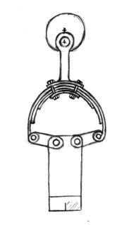
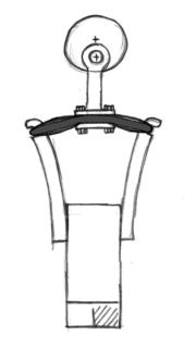
 DuPont : Champion Bow Spring
Many makers used this style bow spring arrangement. Most had leather straps in place of the toggles but these give a similar action when applied against springs. Straps provided a method of tensioning the spring by adjusting their length. As shown the springs must be properly arced for the preload and there is no adjustment. Some makers have used multiple holes in the toggle links but these produce large changes in tension.
A turnbuckle type toggle link can be used but is a complicated part requiring a yoke on one end and left and right hand screws as well as a locking mechanism. They also need considerable length as the adjustment range is a small part of the length.
Two advantages of this arrangement is the reduction of pivot points and the replacement of the link arms with the springs. See: Bow Spring Linkage From the CR-JYH article for more details.

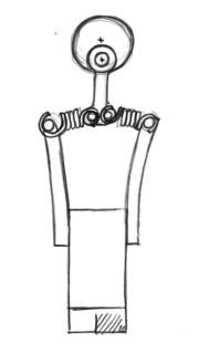
Reverse Bow Spring
There are drawings of the Kerrihard with the spring on the ram but it is not known if any were built. If pre-tensioning is not sufficient, this would either require a turnbuckle toggle adjustment OR spring stiffener arrangement.
The advantage of this arrangement is it reduces non-working reciprocal weight adding it to the ram. Combined with replacing the link arms with the springs this is a very efficient mechanical arrangement.

Dempsey Quarter Elliptic
Similar to the reverse bowspring this arrangement can be adjusted with shim plates or pivots and screws as on the anvilfire X1 power hammer. This has the advantages of the DuPont linkage without the disadvantage of all that hard to balance inefficient reciprocal mass typical on Little Giants and other hammers.
The "quarter elliptic" spring is a common leaf spring cut in half. These half springs were used on various British cars including 1950's Austins.

Dempsey Rubber Band
This is an untested, unproven design requiring a heavy elastomer "spring". It has two rigid "ram horns" with a heavy rubber band or elastomer stretched between. This could be heavy natural rubber or a nylon rope. Much testing would be required and heating of the elastomer would probably be an issue as it was on the largest Bradley hammer with a leather strap ram linkage.
This is similar to the old leather belting straps that linked to the ram on many hammers except that this puts the arms on the ram for more efficient use of mass and uses a stretchy connecting material.
In this design the elastomers are the toggle links, pivots and springs. This is an absolute minimalist arrangement.

Dempsey Ram Coil
This is similar to the above but uses 4 tension springs (a pair on each side) in place of the rubber bands. This is another untested unproven design but would surely work on a light hammer.
Tensioning would need to be guessed at (8 to 10 x the ram weight) and the preload performed when bolting on the arms or an adjustment system used where the arms attach to the ram. Due to the rotation at the ends the springs should ride on bronze bushings to reduce wear.
This is not quite as minimalist as the rubber band but is very close.

Pogo Stick (non-DuPont)
This is a design that comes up repeatedly and has been built by a number of people. It is more complicated to build than shown and has few merits other than it WILL work in a limited manner. However, the springs need to be quite stiff and there is less "snap" than in DuPont style linkages.
In general this is an energy wasting linkage that trys to lift the machine off the ground with every stroke. Unless the springs are balanced exactly for the mass of the ram and speed of the machine no usable work can be gotten from it.
Spring Helve or Feather Hammer
Springs are most often straight or slightly bowed and have extra leaves on both top and bottom. Couplings vary most often clamping to the springs and the front of many hammers simply have the leaf spring going through a slot in the ram. Sometimes this has roller bearings but most often not.
The advantage of this arrangement is that it results in a short machine. The disadvantage is that it has a large footprint compared to vertically configured hammers.
There are many other power hammer linkages but the DuPont and its variations have been the most successful followed by the spring helve. While Bradley and a few others made many helve hammers the dynamics of the snubbing systems were complicated and difficult to make work properly.