anvilfire! Power hammer Page 10   Page 1   EC-JYH Supplement    Page 11 Bow Springs  

East Coast Junk Yard Hammer Idea Sketch II

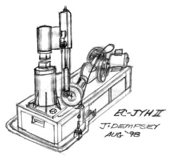
EC-JYH-II Design Sketch (not built)

I've described the concrete filled foundation of this design several times on the Guru page and thought it was time I got this sketch posted. This design was inspired by queries from a fellow I had a long off-line discussion about putting the axle down low so it was easier to build and not so top heavy. His questions were, "Can the axle be put below the anvil and will the shock linkage work this way?" I had to think about it for a while but YES the shock linkage works exactly the same. I combined this idea with the concrete base idea I had been playing with.

Please note that the concrete adds a LOT of mass to this machine but does not replace the anvil!

Reasons for the concrete base:
  • I was lucky finding a big (heavy) 2" (50mm) thick plate for the base of the first EC-JYH.
  • Luck helps on this kind of project but should not be relied upon for major components.
  • The extra mass will act as an above ground isolation pad and add to the stability of the hammer.
  • Concrete is relatively cheap, available everywhere and requires no special tools or machinery.


  • The base is made of a welded light angle iron frame (corner protection) with anchors and support plates for the other parts. The entire machine would be built on the base frame with the anchors and such attached to reinforcing bar within the frame. After everything is properly positioned and tacked into place the machinery would be removed, form boards installed and the frame filled with concrete. The result would be a heavy monolithic base that could substitute for a special foundation. This may NOT be the best construction method but it puts the JYH within the grasp of more builders.

    Preliminary Specifications:
  • 40 Pound Ram and a Single Shock Absorber NOTE: We do not recomend the shock absorber linkage. We tested it, proved it worked but very inefficiently.
  • 400 Pound or greater anvil setting on concrete base as described above.
  • Tubular column guide system with internal adjustable height spring cushion.
  • Small Truck axle (instead of heavy car) with as high a reduction ratio as can be found (and is cheap).
  • 3/4 or 1HP single phase motor
  • -
  • Estimated weight 1,500 to 2,000 pounds

  • Further Comments:
    This is another machine that should be buildable on a $200 budget or less.
    The drive is set at an angle so that it fits in the smallest possible rectangle.
    The base as shown is rectangular but could be any polygon or even ovoid.
    The anvil may need to be set down into the base depending on the diameter material available but the support should be at the top for strength and load distribution.

    The guide system will probably be two pieces of angle with 45° flanges so that it can be easily adjusted to the tubular guide. This is actually easier than finding telescoping tubing or fabricating a box section to fit.
    Copyright © 1998 - 2007 by Jock Dempsey, DEMPSEY'S FORGE
    Page 10