(l')eteau,
Schmiedeschraubstock,
tornillo de banco,
tornillo de pie,
skruvstycke,
vinkelskruvstycke,
bankschroef,
beenskroef,
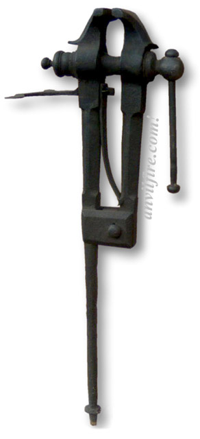
The blacksmith leg vise or "solid box vise" is one of the most important tools in the blacksmiths shop.
It firmly holds hot iron while it is hammered, chiseled or twisted.
These are the only vise that is designed to take this kind of use day in and day out.
A small 30 pound blacksmith's vise can survive pounding that would wreck a much heavier cast iron bench vise.
Three things make a blacksmith's vice special.
One is that they are forgings, not cast iron or ductile iron.
The second is the leg which provides support to the floor or from a sunken post.
The last is the hinge, while not a perfect way to construct a vice the pin joint is durable and can take a considerable beating.
If sheared it is easy to replace.
These things all combine into a tool that can take decades of heavy use and abuse.
Most in use are one to two hundred years old.
Some of these vises were made by specialists such as Atwood of Stourbridge England, Steel City and Columbian in the U.S. and others were made in anvil manufacturing plants such as
Mousehole Forge and Peter Wright in England and
Fisher-Norris and others in North America.
The design of these vises right down to the last chamfer seems to have been perfected in the 1600's and remained more or less the same until the 20th century.
The bodies are forged wrought iron or mild steel and they have hard steel surfaces welded into the jaws.
The jaws have little or very shallow serrations which are generally worn off.
The "solid box" is a Peter Wright development. The "box" is the threaded nut and flange.
Early vises had built up boxes made by forge welding and brazing parts together including making the threads by brazing a coil inside a tube.
The value of and demand for vises was so great that this primative method of making a nut (female thread) was used for three centuries or more.
The Peter Wright patent of 1863 was for a solid (one piece) box, threaded using modern methods.
While this was a big change in manufacturing leg vises there was debate over the value of the patent as it mearly applied current machines and nut making technology to a specific product.
Around the turn of the 20th Century during the hey-day of the blacksmith shop in North America
these tools were considered so standard a commodity that they were sold without reference to manufacturer.
Very few were even marked with the maker's name.
Size is best defined by weight as there is some variation in jaw size from manufacturer to manufacturer.
They were sold by the pound and are still best judged by the pound.
Note that new manufacturers no longer follow these "standard" proportions and a modern
import 8" vise only weighs 120 pounds compared to the 200 to 250 pounds of the old vises.
Vise Size and Weight:
In my 1894 catalog, the leg vise weight and jaw width are listed thusly (chart below), and I believe they are referring to the Peter Wrights. [ chart moved below ]
As Jock pointed out, there are going to be variations, even by the same manufacturer.
For example, I saw in Scotland a Peter Wright vise that had a 6-7/8" jaw and a 20" long spring.
The legs had a very slight chamfer.
I have one with the same jaw width and a 17" spring. The chamfering is much more pronounced.
Frank Turley
- Saturday, 06/21/03 12:34:25 GMT
| English Solid Box Vises
|
| Weight |
Jaw |
| 30 |
3.5 |
| 35 |
3.75 |
| 40 |
4 |
| 45 |
4.25 |
| 50 |
4.5 |
| 55 |
4.75 |
| 60 |
5 |
| 65 |
5 |
| 70 |
5.25 |
| 75 |
5.25 |
| 80 |
5.5 |
| 85 |
5.5 |
| 90 |
5.75 |
| 95 |
5.75 |
|
|
| Weight |
Jaw |
| 100 |
6 |
| 110 |
6 |
| 120 |
6.5 |
| 130 |
6.5 |
| 140 |
7 |
| 150 |
7 |
| 160 |
7.25 |
| 170 |
7.25 |
| 180 |
7.5 |
| 190 |
NA |
| 200 |
7.75 |
| 220 |
8 |
| 240 |
8 |
| 270 |
+8, 8 |
|
| Weight in Pounds Jaw width in inches.
|
|
|
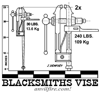
The diagram above shows the difference in proportions between a 30 pound and a 240 pound vise.
Most of the vise is in direct proportion with a few adjustments. The most noticeable is the length of the leg.
The screws and handles step up in size every forth size increase so a 45 lb. and 55 lb. vise will both have the same length handle.
The height of most these vices from the top of the jaws to the flange on the leg is 39" (990 mm), +/- 1" (25mm).
|
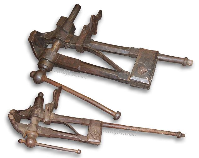
Pair of English Blacksmith Leg Vices from the Parlett Farm Museum sale.
Photos from Stewartthesmith
Proportionality in Leg Vises
The images above show some of the size range in Blacksmiths Leg vises.
Note that everything is proportional except the overall height which is fixed at about 39".
Being made in over 25 weight based sizes these tools had different sized parts for almost every size.
This makes replacement parts such as screws boxes (nuts) and springs very specific to a given vise.
Multiply these differences by dozens of manufacturers and there could be thousands of variations.
Screws for these vises range from about 1" to 1-1/2" diameter in 1/16" increments or a dozen sizes.
Some probaly span a couple weights similar to jaw widths. But that is still a large number of sizes.
 Mounting Leg Vises:
 Sturdy is important.
When I have a chance to mount a vise on a bench the bench is anchored to the wall and the floor first.
Then I make a plate to anchor to the wall with a piece of angle iron extending from it.
This is mounted under the bench top and has a hole for at least one of the vise bolts to go through.
The foot of a leg vise needs a load distribution pad. Usually a metal plate with a hole for the spike. OR a good hard stone as Thomas has suggested.
The load pad can rest on concrete, wood or brick. On a dirt floor it was common to set a post deep in the earth next to the vise mounting post for the foot to set on.
These were cut above the floor OR below as needed. Use a good creosoted or salt treated post, seal the post with tar for longevity.
In a permanent shop with a dirt floor or outdoors it was common to mount leg vises on a post set in the ground.
The setup to the right has the post set in 300 pounds of concrete.
The block under the foot should have also been set in the ground as this is what takes the vertical hammering load.
Modern shops most often use steel posts either bolted to the floor OR set in concrete very similar to the wooden post shown.
These have a top flange and sometimes a small bench area and tool racks.
Freestanding vice stands have little utility unless they are VERY heavy or like the stand below the user stands on it preventing movement.
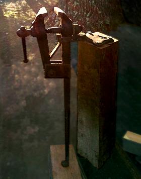
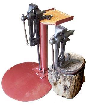 The two stands shown here were designed for portability.
The new steel stand works very well but needs some ribs to extend out on the base plate to reduce springiness. The reason the vise is set to the back of the plate is so that you stand on the plate when using the vise. You CAN NOT make the vise move when you are standing on its base! This baseplate is some 3/8" scrap I had. It would seem stiff enough without ribs or diagonals but it is not. I suspect that 1/2" or thicker is needed to avoid the springiness.
The two stands shown here were designed for portability.
The new steel stand works very well but needs some ribs to extend out on the base plate to reduce springiness. The reason the vise is set to the back of the plate is so that you stand on the plate when using the vise. You CAN NOT make the vise move when you are standing on its base! This baseplate is some 3/8" scrap I had. It would seem stiff enough without ribs or diagonals but it is not. I suspect that 1/2" or thicker is needed to avoid the springiness.
The stump mounted vise looks cool but was a bad design. It acts like a rolly-poly clown toy and is not very steady. One twice as big might have been OK. Over the years the edges of the stump have worn round making the problem worse. My plan is to mount this stump on a piece of plate like the other vise. The larger wheel base will prevent tipping and be very solid. It will also prevent further wear on the stump.
Portable vise mounts either need to be large OR heavy. I think most brake drum mounts are too small and light. Avoid welding to the vise if you can.
One very interesting vise mount I saw recently was on a hitch receiver.
Slip off the trailer ball and slip in the vise. Anchoring to the bumper on a heavy vehical is about as solid as you can get.
- guru
- Thursday, 06/19/03 03:27:23 GMT
Types and Age of Blacksmith Vises:
Few of these tools were marked by the manufacturer but there were some general differences in style.
The old English vices had more and finer decorative lines.
The chamfers on the legs were deep and produced a square section turned 45°.
The nuts and screw were turned and had decorative molding and lines.
The oldest vises had a rectangular tenon on the bench bracket that pierced the back leg and spring.
A pin in front of the spring held the vise to the bracket.
Later vises (after about 1838) had wrap around strap brackets held in place with a clip and wedge system. Some of the latest American vises had U-bolt mounts.
These bench brackets were three different types. One that is definitely English is a tapered diamond shape with bean ends for the bolts.
The drop forged American style is a simplified version of this. Then there is the split "rams horn" type bracket that was derived from the early tenon type.
Most surviving American made vises tend to be the late drop forged types and some have cast parts. There is less decoration on the late American vises, no or low chamfers on the legs and no turning on the nut and screw.
-guru
Identification of Vises:
It is more difficult to find out about old leg vises than anvils, because there were fewer markings. When Peter Wright did mark their vises, they did so on top of the screw box body with P.WRIGHT PATENT SOLID BOX. These were in three lines, stamped in small, serifed letters and were often obliterated by wear and rust. The stamped letters were a matter of pride and the result of a break through in technology. The earlier boxes, I assume throughout Europe, were composites made up of multiple "rings" forge brazed around a forge welded tube. The square threads consisted of a coil brazed inside the tube. Normally, brass spelter was used rather than copper, as the brass melts earlier than copper. After brazing, the internal threads were cleaned and the external box was lathe turned. On close inspection, one can see evidence of brass and/or slight separations where the rings are joined.
The Peter Wright firm figured a way to eliminate all the composite brazing business, and was able to make a solid box with internal threads.
The Peter Wright vises exported to the U.S. most often had deeply chamfered legs. When I was in Australia, the PW vises most often had very slight chamfers on the legs. Some of the Australian PWs had the royal coat of arms stamped on them. I suspect that the Australian imports were made at a later date that the U.S. ones. In all other respects, the Australian and U.S. Peter Wright vises appear to have the same conformation.
Frank Turley - 05/29/08
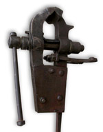
Parts:
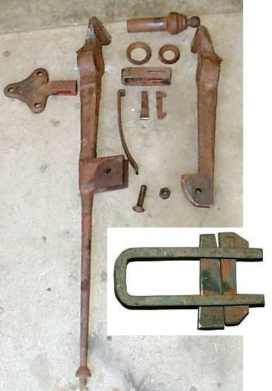
Missing from the laid out parts is the screw - my mistake (see below).
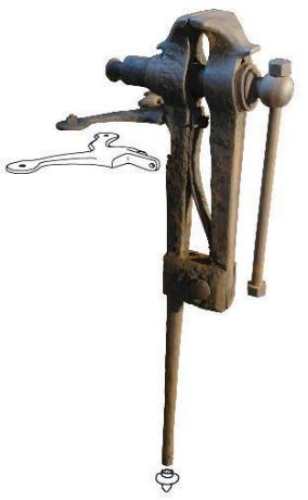
The vice to the right is a tennon mount type from Old Millstone Forge in New Jersey, USA and dates from about 1820.
This vice has been repaired by replacing the screw handle with a bar with nuts threaded onto the ends.
Someone recently cut off the foot to clear a new floor. . .
Vise Screws:
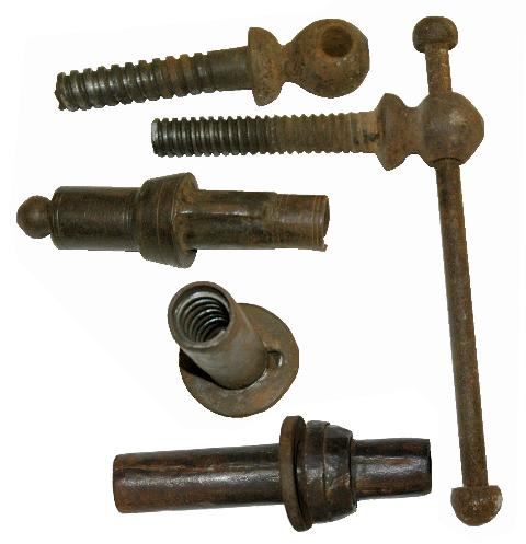
These are the Boxes and Screws from two vices that Dave Baker and I photographed one evening. One appears to be a solid box and the other obviously a pieced box that has missing parts.
The tube of pieced box is actually rolled from about 1/4" thick material. You can see the weld line in the bottom view. The anti-rotation key is missing but you can see where it fit into the first ring of the stack that was the back of the box. The short coarse thread screw fit this box. The fine (worn out) screw fit the other box.
The fact that these parts were made by a combination of forge welding and brazing is pretty amazing. At this time the screw threads were probably hand turned on a lathe. Even when Maudslay first started making his geared screw turning lathes the master screws were made by hand. He used knife edges to make a spiraling line the length of the screw then followed it by hand making it deeper with multiple passes.
The "Solid Box" patent was probably based on Wrights early use of steam hammers and dies in their trade as his anvil patent shows. This "invention" was more the result of advances in manufacturing machines than an advance in vice design.
Machine Methods:
The solid box shown has been center drilled in the knob end.
To support this piece in the lathe it would need to be supported in a steady rest and tied against the drive plate with leather thongs (a common method of the time).
Note the area in front of the key that has been turned down.
This is a trued surface for the part to run in the steady rest.
Otherwise there would be no reason for machining this surface.
SO, the order of operations to make this solid box as thus.
1) Forge the solid blank
2) Center drill both ends
3) Machine a clean area for the steady rest.
4) Setup with a center and steady rest
5) Drill the hole.
6) Thread the screw hole (tap or chase).
7) Stamp name or ID.
8) From one advertisement for Peter Wright Solid Box vises, case harden
The only marked box I have seen is one I have with a Brooks & Amritage marking in an oval.
This required a rolling marking die to put the large logo on a curved surface.
Vise Brackets
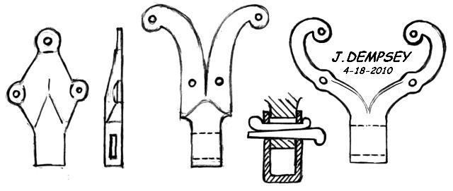
Three types of English Vise Bracket
I have observed three styles of mounting brackets on these old English vises.
One is a diamond shape with round extrusions at the corners where the bolts go.
The other two have split and scrolled ends.
On one type they curve outward slightly with large bean ends.
They taper in thickness but almost none in width.
On the other they taper in width and spread out into a heart shape and have small bean ends for the bolts as well as bolt holes about mid way out the arms.
Split types are seen on both wrap around and older tennon type mounts.
I suspect the styles are indicative of various manufacturers but I could not say which.
These are normally very clean forgings with chamfers or radiused edges and no hammer marks.
They were production hand forgings and thus kept fairly simple and clean.
Hand made replacements could be quite a bit fancier with more details.
The diamond type is nearly the design that was later converted to a drop forging or casting in a much uglier triangular but utilitarian form.
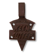 The KEEN KUTTER vise
 bracket is perhaps the most unusual of all as it incorporates the entire KEEN KUTTER logo in crisp raised letters.
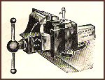
 German Blacksmith Vise
Another traditional bench bracket style and a technically different leg vise.
Vise Heights and mounting:
There are different heights for different purposes. The normal for general work is to have the top of the
jaws at about 39" (990 mm) for work while standing. This is the height of most blacksmith leg vises and is good for sawing, chiseling
and heavy filing. Blacksmith vises of all sizes are usually this height from jaw to leg flange. If the leg flange is set on
something above the ground the height will be a little higher. If you are shorter or taller than average then the vise may want
to adjusted to suit.
One of the handiest most used vises in my shop is a heavy 6-1/2" 130 pound Prentis chipping vise mounted on a 39" (990 mm) tall
bench. This puts the jaws at 49" (1245 mm). This is a high vise but it is convenient for close work or things like planing a board that
you want to "eyeball" for straightness and for heavy bending at shoulder level where you pull with your all. I've moved this
vise and bench twice and set it up the same way because I always liked it. Note, I am 5'9" (1753 mm)tall.
This most important thing about mounting vises is that they are on a sturdy immovable stand or bench.
For work sitting you may want a vise as low as 28" (711 mm) or as high as 36" (914 mm). However, if sitting on a tall chair the standard 39"
height works well.
Note that a good portion of the work done at a blacksmith vise is hammering. Bench vises will not withstand this type of
use. Even the very expensive unbreakable forged steel vises will end up with bent guide arms or broken screws.
A little 30 to 50 pound blacksmiths leg vise will withstand abuse that takes a 120 to 150 pound HD bench vise to withstand.
Blacksmith vises generally survive to wear out where most bench vises end up broken at the end of their much shorter lives.
Vise Lubrication:
Vise screws are often overlooked when lubricating machinery and the result is a hard to use vise or worn out screw.
High pressure lubricants such as Never-Seize work great on vise screws.
Don't forget to put a little under the thrust washer.
References and Links


Some of these vises were made by specialists such as Atwood of Stourbridge England, Steel City and Columbian in the U.S. and others were made in anvil manufacturing plants such as Mousehole Forge and Peter Wright in England and Fisher-Norris and others in North America. The design of these vises right down to the last chamfer seems to have been perfected in the 1600's and remained more or less the same until the 20th century. The bodies are forged wrought iron or mild steel and they have hard steel surfaces welded into the jaws. The jaws have little or very shallow serrations which are generally worn off.
The "solid box" is a Peter Wright development. The "box" is the threaded nut and flange. Early vises had built up boxes made by forge welding and brazing parts together including making the threads by brazing a coil inside a tube. The value of and demand for vises was so great that this primative method of making a nut (female thread) was used for three centuries or more. The Peter Wright patent of 1863 was for a solid (one piece) box, threaded using modern methods. While this was a big change in manufacturing leg vises there was debate over the value of the patent as it mearly applied current machines and nut making technology to a specific product.
Around the turn of the 20th Century during the hey-day of the blacksmith shop in North America these tools were considered so standard a commodity that they were sold without reference to manufacturer. Very few were even marked with the maker's name. Size is best defined by weight as there is some variation in jaw size from manufacturer to manufacturer. They were sold by the pound and are still best judged by the pound.
Note that new manufacturers no longer follow these "standard" proportions and a modern import 8" vise only weighs 120 pounds compared to the 200 to 250 pounds of the old vises.
Vise Size and Weight: In my 1894 catalog, the leg vise weight and jaw width are listed thusly (chart below), and I believe they are referring to the Peter Wrights. [ chart moved below ]
As Jock pointed out, there are going to be variations, even by the same manufacturer. For example, I saw in Scotland a Peter Wright vise that had a 6-7/8" jaw and a 20" long spring. The legs had a very slight chamfer. I have one with the same jaw width and a 17" spring. The chamfering is much more pronounced.
Frank Turley - Saturday, 06/21/03 12:34:25 GMT
The diagram above shows the difference in proportions between a 30 pound and a 240 pound vise. Most of the vise is in direct proportion with a few adjustments. The most noticeable is the length of the leg. The screws and handles step up in size every forth size increase so a 45 lb. and 55 lb. vise will both have the same length handle.
The height of most these vices from the top of the jaws to the flange on the leg is 39" (990 mm), +/- 1" (25mm).
Pair of English Blacksmith Leg Vices from the Parlett Farm Museum sale.
Photos from Stewartthesmith
Proportionality in Leg Vises
The images above show some of the size range in Blacksmiths Leg vises. Note that everything is proportional except the overall height which is fixed at about 39". Being made in over 25 weight based sizes these tools had different sized parts for almost every size. This makes replacement parts such as screws boxes (nuts) and springs very specific to a given vise. Multiply these differences by dozens of manufacturers and there could be thousands of variations.Screws for these vises range from about 1" to 1-1/2" diameter in 1/16" increments or a dozen sizes. Some probaly span a couple weights similar to jaw widths. But that is still a large number of sizes.
The foot of a leg vise needs a load distribution pad. Usually a metal plate with a hole for the spike. OR a good hard stone as Thomas has suggested. The load pad can rest on concrete, wood or brick. On a dirt floor it was common to set a post deep in the earth next to the vise mounting post for the foot to set on. These were cut above the floor OR below as needed. Use a good creosoted or salt treated post, seal the post with tar for longevity.
In a permanent shop with a dirt floor or outdoors it was common to mount leg vises on a post set in the ground. The setup to the right has the post set in 300 pounds of concrete. The block under the foot should have also been set in the ground as this is what takes the vertical hammering load.
Modern shops most often use steel posts either bolted to the floor OR set in concrete very similar to the wooden post shown. These have a top flange and sometimes a small bench area and tool racks.
Freestanding vice stands have little utility unless they are VERY heavy or like the stand below the user stands on it preventing movement.
 The two stands shown here were designed for portability.
The new steel stand works very well but needs some ribs to extend out on the base plate to reduce springiness. The reason the vise is set to the back of the plate is so that you stand on the plate when using the vise. You CAN NOT make the vise move when you are standing on its base! This baseplate is some 3/8" scrap I had. It would seem stiff enough without ribs or diagonals but it is not. I suspect that 1/2" or thicker is needed to avoid the springiness.
The two stands shown here were designed for portability.
The new steel stand works very well but needs some ribs to extend out on the base plate to reduce springiness. The reason the vise is set to the back of the plate is so that you stand on the plate when using the vise. You CAN NOT make the vise move when you are standing on its base! This baseplate is some 3/8" scrap I had. It would seem stiff enough without ribs or diagonals but it is not. I suspect that 1/2" or thicker is needed to avoid the springiness.
The stump mounted vise looks cool but was a bad design. It acts like a rolly-poly clown toy and is not very steady. One twice as big might have been OK. Over the years the edges of the stump have worn round making the problem worse. My plan is to mount this stump on a piece of plate like the other vise. The larger wheel base will prevent tipping and be very solid. It will also prevent further wear on the stump.
Portable vise mounts either need to be large OR heavy. I think most brake drum mounts are too small and light. Avoid welding to the vise if you can.
One very interesting vise mount I saw recently was on a hitch receiver. Slip off the trailer ball and slip in the vise. Anchoring to the bumper on a heavy vehical is about as solid as you can get.
- guru - Thursday, 06/19/03 03:27:23 GMT
Types and Age of Blacksmith Vises: Few of these tools were marked by the manufacturer but there were some general differences in style. The old English vices had more and finer decorative lines. The chamfers on the legs were deep and produced a square section turned 45°. The nuts and screw were turned and had decorative molding and lines. The oldest vises had a rectangular tenon on the bench bracket that pierced the back leg and spring. A pin in front of the spring held the vise to the bracket.
Later vises (after about 1838) had wrap around strap brackets held in place with a clip and wedge system. Some of the latest American vises had U-bolt mounts. These bench brackets were three different types. One that is definitely English is a tapered diamond shape with bean ends for the bolts. The drop forged American style is a simplified version of this. Then there is the split "rams horn" type bracket that was derived from the early tenon type.
Most surviving American made vises tend to be the late drop forged types and some have cast parts. There is less decoration on the late American vises, no or low chamfers on the legs and no turning on the nut and screw.
-guru
Identification of Vises:
It is more difficult to find out about old leg vises than anvils, because there were fewer markings. When Peter Wright did mark their vises, they did so on top of the screw box body with P.WRIGHT PATENT SOLID BOX. These were in three lines, stamped in small, serifed letters and were often obliterated by wear and rust. The stamped letters were a matter of pride and the result of a break through in technology. The earlier boxes, I assume throughout Europe, were composites made up of multiple "rings" forge brazed around a forge welded tube. The square threads consisted of a coil brazed inside the tube. Normally, brass spelter was used rather than copper, as the brass melts earlier than copper. After brazing, the internal threads were cleaned and the external box was lathe turned. On close inspection, one can see evidence of brass and/or slight separations where the rings are joined.
The Peter Wright firm figured a way to eliminate all the composite brazing business, and was able to make a solid box with internal threads.
The Peter Wright vises exported to the U.S. most often had deeply chamfered legs. When I was in Australia, the PW vises most often had very slight chamfers on the legs. Some of the Australian PWs had the royal coat of arms stamped on them. I suspect that the Australian imports were made at a later date that the U.S. ones. In all other respects, the Australian and U.S. Peter Wright vises appear to have the same conformation.
Frank Turley - 05/29/08
Parts:
Missing from the laid out parts is the screw - my mistake (see below). The vice to the right is a tennon mount type from Old Millstone Forge in New Jersey, USA and dates from about 1820. This vice has been repaired by replacing the screw handle with a bar with nuts threaded onto the ends. Someone recently cut off the foot to clear a new floor. . .
Vise Screws:
The tube of pieced box is actually rolled from about 1/4" thick material. You can see the weld line in the bottom view. The anti-rotation key is missing but you can see where it fit into the first ring of the stack that was the back of the box. The short coarse thread screw fit this box. The fine (worn out) screw fit the other box.
The fact that these parts were made by a combination of forge welding and brazing is pretty amazing. At this time the screw threads were probably hand turned on a lathe. Even when Maudslay first started making his geared screw turning lathes the master screws were made by hand. He used knife edges to make a spiraling line the length of the screw then followed it by hand making it deeper with multiple passes.
The "Solid Box" patent was probably based on Wrights early use of steam hammers and dies in their trade as his anvil patent shows. This "invention" was more the result of advances in manufacturing machines than an advance in vice design.
Machine Methods: The solid box shown has been center drilled in the knob end. To support this piece in the lathe it would need to be supported in a steady rest and tied against the drive plate with leather thongs (a common method of the time). Note the area in front of the key that has been turned down. This is a trued surface for the part to run in the steady rest. Otherwise there would be no reason for machining this surface.
SO, the order of operations to make this solid box as thus.
1) Forge the solid blank
2) Center drill both ends
3) Machine a clean area for the steady rest.
4) Setup with a center and steady rest
5) Drill the hole.
6) Thread the screw hole (tap or chase).
7) Stamp name or ID.
8) From one advertisement for Peter Wright Solid Box vises, case harden
The only marked box I have seen is one I have with a Brooks & Amritage marking in an oval. This required a rolling marking die to put the large logo on a curved surface.
Vise Brackets
Three types of English Vise Bracket
I have observed three styles of mounting brackets on these old English vises. One is a diamond shape with round extrusions at the corners where the bolts go. The other two have split and scrolled ends. On one type they curve outward slightly with large bean ends. They taper in thickness but almost none in width. On the other they taper in width and spread out into a heart shape and have small bean ends for the bolts as well as bolt holes about mid way out the arms.
Split types are seen on both wrap around and older tennon type mounts.
I suspect the styles are indicative of various manufacturers but I could not say which.
These are normally very clean forgings with chamfers or radiused edges and no hammer marks. They were production hand forgings and thus kept fairly simple and clean. Hand made replacements could be quite a bit fancier with more details.
The diamond type is nearly the design that was later converted to a drop forging or casting in a much uglier triangular but utilitarian form.
The KEEN KUTTER vise bracket is perhaps the most unusual of all as it incorporates the entire KEEN KUTTER logo in crisp raised letters.
German Blacksmith Vise
Another traditional bench bracket style and a technically different leg vise.
Vise Heights and mounting:
There are different heights for different purposes. The normal for general work is to have the top of the jaws at about 39" (990 mm) for work while standing. This is the height of most blacksmith leg vises and is good for sawing, chiseling and heavy filing. Blacksmith vises of all sizes are usually this height from jaw to leg flange. If the leg flange is set on something above the ground the height will be a little higher. If you are shorter or taller than average then the vise may want to adjusted to suit.One of the handiest most used vises in my shop is a heavy 6-1/2" 130 pound Prentis chipping vise mounted on a 39" (990 mm) tall bench. This puts the jaws at 49" (1245 mm). This is a high vise but it is convenient for close work or things like planing a board that you want to "eyeball" for straightness and for heavy bending at shoulder level where you pull with your all. I've moved this vise and bench twice and set it up the same way because I always liked it. Note, I am 5'9" (1753 mm)tall.
This most important thing about mounting vises is that they are on a sturdy immovable stand or bench.
For work sitting you may want a vise as low as 28" (711 mm) or as high as 36" (914 mm). However, if sitting on a tall chair the standard 39" height works well.
Note that a good portion of the work done at a blacksmith vise is hammering. Bench vises will not withstand this type of use. Even the very expensive unbreakable forged steel vises will end up with bent guide arms or broken screws.
A little 30 to 50 pound blacksmiths leg vise will withstand abuse that takes a 120 to 150 pound HD bench vise to withstand. Blacksmith vises generally survive to wear out where most bench vises end up broken at the end of their much shorter lives.
Vise Lubrication:
Vise screws are often overlooked when lubricating machinery and the result is a hard to use vise or worn out screw. High pressure lubricants such as Never-Seize work great on vise screws. Don't forget to put a little under the thrust washer.
References and Links
The anvilfire VISE (Vice) gallery
Screw Vises modern and antique.