|
| |||||||||

| |||||||
| |||||||
| |||||||
|
| ||||||
|
| ||||||
| |||||||
| |||||||
| |||||||
| |||||||
| |||||||
| |||||||
| |||||||
| |||||||
| |||||||
| |||||||
| |||||||
| |||||||
| |||||||
| |||||||
|
| |||||||

|

|
DIY Power HammersNotes on Designing and building a Mechanical Power Hammer
With the explosion in hobby smithing and part time blacksmithing there has been a great interest in building forging machines or power hammers.
There are two schools of construction JYH (Junk Yard Hammers) and DIY (Do-It-Yourself).
JYH construction is a philosophy of using found and scrounged materials, spending the least possible money.
It requires both scrounging and engineering skills.
The engineering skills (or an innate sense of mechanics) are necessary to repurpose found or accumulated items rather than very specific items.
DIY construction is based on plans or a preconceived set of parts and materials obtained new or used.
While scrap can be used it needs to fit the plan rather than the plan being adopted to found materials.
Most metalworkers can build a DIY hammer but many do not have the engineering or (imagineering) skills to build a true JYH.
Before building a mechanical power hammer you need to understand how they work. The basics.
ITEM 1 Motor and Drive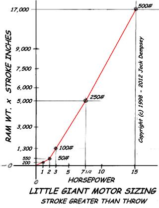 The necessary motor can vary in horsepower depending on the size of the hammer and how fast it operates.
In general a 1HP motor will run a small hammer under 100 pounds and a 1.5 to 2 HP motor is needed to run a 100 pound or greater hammer.
Higher HP motors may be used and have greater durability than if run at maximum capacity.
Hammers over 125 pounds are rarely JYH or DIY class machines so large motors are not needed.
The necessary motor can vary in horsepower depending on the size of the hammer and how fast it operates.
In general a 1HP motor will run a small hammer under 100 pounds and a 1.5 to 2 HP motor is needed to run a 100 pound or greater hammer.
Higher HP motors may be used and have greater durability than if run at maximum capacity.
Hammers over 125 pounds are rarely JYH or DIY class machines so large motors are not needed.
Reverse engineering such as using the chart to the right can be helpful. However, one must understand the context. Little Giant used standard industrial duty motors starting at 1HP. As hammers increased in size so did the motor size but not necessarily according to need.
If this chart were directly proportional a 25# hammer would need 1/10th the HP of a 250# hammer.
That would be 3/4 HP.
Motors are also sized according to inertia. Starting a heavy load requires inertia rather than horsepower. Once the load is moving horsepower is required to keep it moving.
This is part of the discrepancy between LG and Fairbanks specs.
The LG ratings are for motors, the Fairbanks for line shafting HP where the starting inertia is not a consideration.
But it is also known that a 50 lb. LG will run on a 1HP motor and our 110 pound anvilfire X1 hammers run snappily with 2HP.
I would not try to run a 25 pound hammer on 1/2 HP but our 40 pound EC-JYH ran on 3/4 HP and the extrapolated Little Giant data says that a 25 pound hammer should run on 3/4HP.
Speed is also part of the HP formula but most hammers run proportionately slower as the size increases. Thus the ram weight to HP for mechanical hammers can be a fairly constant ratio.
Horsepower = Ram Weight in Pounds / 66The Fairbanks data rounds UP from the formula above except at 250 pounds which should be 4 HP (we rounded up to 5 the nearest standard motor): At 25 pounds the formula returns a little over 1/3 HP thus Fairbanks rounded to 1/2 HP. We split the difference between Fairbanks and Little Giant thus 3/4 HP in the MIN column. However, there are those who push the performance of these small hammers with heavier springs, running them much faster than originally intended with much higher horsepower motors. Multiple Motors The junk yard builder, DIY and the home shop operator often have a difficult time finding cheap single phase motors to run their machinery. In most industrial applications 3PH power is required so most machines and many used or discount motors over 1HP are 3PH. These can be run on a phase converter but not without some expense. An option for the DIY builder is to put TWO motors on one machine. The motors CAN even be different sizes! This works but only under certain conditions. 1) The motors must be the same type (IE induction). 2) The motor's rated full load RPM's are identical. 3) The coupling method or pulley's are identical. Common induction electric motors operate at a "slip" speed under load that is slower than the nominal syncrounous rating. This means an 1800 or 1200 RPM motor develops its rated power at something less than syncrounous. That is why the name plate RPM ratings on motors are odd values, 1780, 1750, 1125. . and so on. These are the slip speeds below the nominal rating. If these match then you can use two motors on the same drive. On the EC-JYH I had two small fractional HP motors, one a 3/4 HP and the other a 1/2 HP. These two motors pulled on the same belt using the same 2" pulley's. This resulted in a combined 1-1/4 HP. Due to needing to slip the belt more to reduce the operating speed we disconnected the smaller motor but left it on the machine! This does not work on every machine and works best when there is a jack shaft. But it would be possible to build a machine running on 2, 3, 4. . motors. Several 1/3 HP motors could be combined to produce 2/3 HP or three to make 1 HP. Normally this is pure junk-yard construction due to being more economical running one motor with one pulley and one belt. But it IS a option. Blows Per Minute (BPM or RPM) The standard motor turns 1800 RPM on 60Hz power and 1200 RPM on 50Hz power. This in turn needs to be slowed down to a maximum of about 300 to 400 RPM for a small hammer, 150 to 250 for a medium hammer, slower if the hammer dynamics are in question. Normally pulleys do this job. On the Tire-Hammer drive it is its own built in reduction (about 6:1) The speed reduction calculations are simple. Large Pulley Diameter divided by Small Pulley Diameter equals the reduction (from 3 to 6 to one). Divide the motor speed by the reduction and you have the maximum speed of the hammer in blows per minute. If you want to be picky you can use the actual motor speed under load (1750 to 1725 for and 1800 RPM motor). But it makes little difference in this application. The average practical reduction using common belts and pulleys is 3:1 but it can be more. When a great deal more is needed then a back shaft and double reduction is used. When calculating a double reduction drive you take the two reduction amounts and multiply them for the total reduction. So, if you have 3:1 and you need 6:1 then you need a second 2:1 reduction set. Or if you need 5:1 you could use 2.5:1 and 2:1. Simple if you understand it.
ClutchA clutching mechanism of some sort is needed. Historically the best power hammer clutch has been the slip-belt type. Other clutch types such as the Little Giant cone clutch are more complicated and are not recommended for constant slipping. A recent development in JYH/DIY clutching mechanism is the "Spare Tire Clutch". All are friction drives and are used to control the speed of the hammer as well as stop and start it. All are tensioned by the power hammer control (foot treadle). On a belt drive an idler (a third pulley) is pressed against the slack side of the belt to tighten it. On a tire hammer the metal drive wheel is pressed against the tire surface.The advantage of the spare tire clutch is that it is cheap and easy to build with junk yard parts. The down side is the compact spares are difficult to change and a whole wheel replacement may be needed when the tire wears out. New replacements are expensive and the demand for used replacements for automobiles is fairly high even though the prices are low. The advantage of the belt clutch is that material types can be varied (cotton, rubber, leather, nylon) and the belt is easy to replace. The down side is that pulleys need guide edges or rims to prevent the belt from sliding off when slack. Common pulleys are not made this way so custom pulleys may be required. V-belts MAY be used but they are not a good as flat belts for slipping to control speed OR to use with a brake. They tend to engage with a jerk and want to run full speed. Cone clutches such as used by Little Giant are expensive and not intrinsically suited for speed control. Little Giant cone clutches require constant oiling and change in performance as the oil coating spins off. For all their expense they do not perform any better than a belt or wheel clutch. None of these drives care which direction they rotate. However, if an idler is used then it should be on the "slack" side of the drive. This is the side opposite the tension or working side of the drive (where the belt pulls against the driven pulley). On a friction wheel (tire hammer) drive the motor pulley wants to be climbing the driven wheel, not pushing it away. While both will work opposite of this they work easier, smoother and better the right direction. Compensation, Ram Speed, Energy returnBecause all three of these factors are performed by the hammer linkage it is one of the least understood parts of a mechanical power hammer. Changes in work height must be automatically compensated for between every hammer blow. In order to hit hard and soft the stroke must increase with speed. And finally the upward motion of the ram must be stopped and the energy that would be wasted by a simple crank mechanism stored and returned on the down stroke. This is done with springs OR springs and toggles.
Compensation for changes in work thickness has two conditions that must be addressed. The first is the change in work height as the metal is forged thinner, the second is different work starting heights (stock size) OR tooling. The first requires a linkage with a spring but if great work height variations are to be accommodated then the linkage must also have a length adjustment mechanism since the spring compensation becomes very inefficient outside a small range. There are two basic spring systems. The spring helve or springhammer, and the toggle and spring. The second can use a leaf spring, coil spring OR rubber elastomer spring and is known as the DuPont linkage for its inventor. Bradley and a few others used rubber springs but were less common than steel springs. The DuPont linkage was used on almost every successful power hammer built in North America in one way or the other. These include, Fairbanks, Little Giant, Bradley, Champion and many others. The spring helve was popular in Europe and has only recently become popular elsewhere due to its simple construction. Each system has pros and cons as well as performing differently. There are other spring systems that we will not discuss in the main of this article. Air hammers are included in the chart below for reference but are not part of this article.
The DuPont LinkageWhile it is not the simplest to build is has numerous advantages. It is the most compact of the mechanical linkages, most efficient and has the widest range of control. However it IS more technical to build to advantage.The advantages of the Dupont and bowspring with toggle linkages are from the horizontal toggles. These vary the mechanical advantage against the spring from infinity to about 70%. It is the middle point of the stroke when the ram floats through that very low spring force that gives the mechanism its unsurpassed action. While builders of spring helves claim the same "snap" as a Dupont linkage hammer the action is just not the same. When properly adjusted for the work height the Dupont linkage hammer hits the work just outside the floating point before there is any lifting force on the ram. This results in a hard positive blow and little or no shock transmitted into the drive. At the top of the stroke the inertia of the ram compresses the spring as the leverage between the spring and ram progressively increases. This change in leverage puts much greater force on the ram at the stopping point and as it accelerates the ram downward than a plain spring with a constant 1 to 1 mechanical ratio. mv²Energy = mass times velocity squared. So increases in velocity are more significant than increases in mass. In mechanical hammers the velocity is determined by RPM, throw and increase in throw, plus the dynamics.Time between blows in a power hammer determine how hard the hammer hits but also the controllability. A hammer that strikes too fast between blows is hard to control for many types of work. It is common practice for the smith to need to rotate the work a specific amount between blows. If he cannot keep up with the machine it is much less useful. Hammers with stroke length adjustment can be run short and fast producing lighter blows or long an slow with heavier blows. Support - The AnvilTo understand anvils you need to imagine them floating in space. If the anvil is the same size as the hammer, when the hammer strikes the anvil will fly away at the same velocity that the hammer struck it, and the hammer will stop (like pool balls). If there was work between the two the work would move but very little energy would go into the work. If the anvil is only twice as big as the hammer it will move away at about half the speed. Double the energy would go into the work. So if one of these small anvils is resting on the ground or floor all that energy is transferred into the ground and wasted in vibration or noise. If that anvil is a piece of structural or pipe much of the energy goes into springing, deflection and vibration (and the ground).
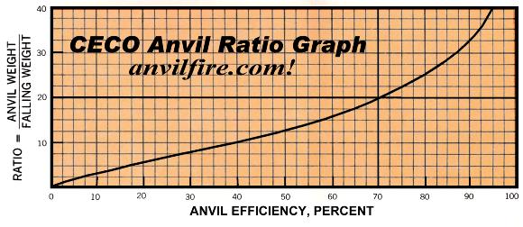 Man vs. Machine At the top of this chart is the 50:1 and greater ratios typical of a heavy smith's anvil. This is in the 96% and 98% efficiency range. When expending skilled human effort a very high efficiency is desired. But when a machine is applying the energy a motor that costs pennies an hour replaces the work of several men. You can afford to waste more of that energy than that of a man's. But the machine can only afford to be less efficient not totally inefficient. Power hammer anvils not only determine the overall efficiency of the machine but the amount of noise and vibration the machine produces. Vibration transmitted through the floor and noise both add to worker fatigue. Thus a less efficient machine results in a less efficient worker. Vibration transmitted into the floor can damage the floor and building, cause object to shake off shelves and produce complaints from neighbors. Ergonomics are also a factor in power hammer anvil design. Most modern smiths like the dies to be higher than on older hammers at about 32" to 34". But there have also been situations where the smith sat on a stool while operating the hammer doing production work. This is possible on the low die hammers but not as easy on a higher die hammer. Part 2 : Power Hammer Linkages Links | ||||||||||||||||||||||||||||||||||||||||||||||||||||||||||||||||||||||||||||||||||||||||||||||||||||||||||||||||||||||||||||||||
 Punch Press: These requirements are why a punch press (a flywheel driven machine with a crank and ram) cannot be used for a power hammer.
A punch press's linkage pushes the ram down a specific distance and then returns.
If the dies in the ram cannot overcome the resistance of the work to be done the machine stops suddenly and SOMETHING breaks.
Ideally the clutch breaks but sometimes the crank or the frame breaks. . . sometimes the punch or die blow up.
Obviously these are not desired results and are the reason why every punch press job must be engineered.
Similar machines (upsetters or forging machines) ARE used for forging but each job must be carefully engineered AND the machines are VERY robust.
These are far beyond the scope of the DIY builder.
Punch Press: These requirements are why a punch press (a flywheel driven machine with a crank and ram) cannot be used for a power hammer.
A punch press's linkage pushes the ram down a specific distance and then returns.
If the dies in the ram cannot overcome the resistance of the work to be done the machine stops suddenly and SOMETHING breaks.
Ideally the clutch breaks but sometimes the crank or the frame breaks. . . sometimes the punch or die blow up.
Obviously these are not desired results and are the reason why every punch press job must be engineered.
Similar machines (upsetters or forging machines) ARE used for forging but each job must be carefully engineered AND the machines are VERY robust.
These are far beyond the scope of the DIY builder.