These anvils are the realization of two
built up anvil drawings I made in 2005 and published in 2007.
This idea stemmed from my
original JYH (Junk Yard Hammer) built in 1998.
We needed to add weight to the ram and ended up attaching pieces of 1" square to the outside of the round ram.
The long bar approach is based on the fact that mass in line with a blow (force) is much more resistant to the blow than distributed mass (load applied from the side of the same mass).
A simple experiment demonstrates this. Take any steel bar 1/2" or larger and 3 feet or longer and strike the end of it on line with the long axis.
The steel will bounce off a larger hammer or the hammer will bounce of heavier steel.
This demonstrates the efficiency of a long mass in line with a force. Now strike the bar in the middle from the side. . . a big difference.
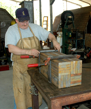
The stack being made above uses commonly available flat bar to build a heavy mass that is nearly equivalent to a difficult to source solid.
In this case we are using 1 x 5 bar to make a 10" square block.
The same method could be applied to build up a 12" square using 1 x 6 bar (or 1/2 x 6 or 2 x 6).
This makes it possible to scrap bar to build a very solid anvil.
In fact it can be done with bar of varying size if carefully arranged.
The critical thing when aligning these pieces to be welded is to create as flat and square as possible surface on one end (the top) so that the anvil cap will come in contact with as much surface as possible.
welding a base plate or flanges on the bottom takes care of most of the error on that end.
If necessary the ends can be hand ground to remove high spots.
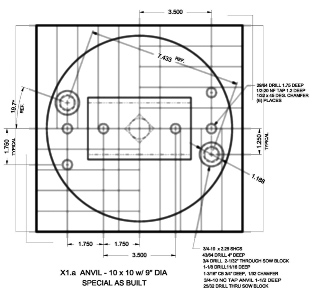
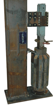
The original plan was to weld the 9" diameter round to the top of the 10" square anvil.
You can see the alignment tack weld in this photo. This was done in a trail assembly with the upper and lower dies in alignment.
The anvil cap was drilled and tapped for the die holder mounting holes and the extra tooling holes before tacking to the anvil.
The large 3/4-10 holes were drilled and tapped in assembly as shown.
This was a late design decision supported by the luck that the holes fell on the centers of two of the 1" plates.
Removal of the anvil cap and die creates an extra 6" of tooling space.
With the top dies that is a total of 10" for special tooling without raising the ram from its lowest position.
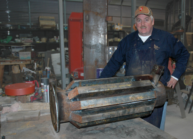
 The second anvil started as a large 7-5/8" diameter piece of steel shafting.
This was just large enough that we had to have someone else saw it to length.
We had several anvils cut and several 1-1/4" thick flanges.
The second anvil started as a large 7-5/8" diameter piece of steel shafting.
This was just large enough that we had to have someone else saw it to length.
We had several anvils cut and several 1-1/4" thick flanges.
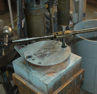
This anvil does not have a cap or sow block. So the die holder holes had to be drilled and tapped directly in the end of the anvil.
At this point we have not added the extra mass so the core is still handleable using a hand truck or walking it across the floor.
It weighs over 400 pounds.
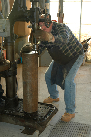
The drill press used to drill both anvils and most of our other parts is an old 25" Champion.
These old back geared machines have a #4 Morse Taper spindle capable of accepting up to a 2" drill bit.
We were lucky to have a 1.5" for drilling many of the parts for this project.
While these machines look antique they are highly efficient hole making machines.
In direct drive they will drill up to 3/4" feeding almost as fast a much smaller bit.
In back gear they will drill up to 1.5" and bore even larger.
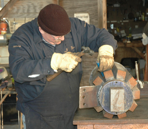
Dave chipping slag off welds. Right - Aligning the anvil to the ram to mark flange holes.
 Adding these 10 pieces of square bar makes a rather stylish looking anvil and added 260 pounds to the 400 pound core for a total of 660 pounds.
This is a little short for a 110 pound hammer but it is what you get when doing a junk yard build.
The square anvil came in at 1050 pounds and was made from all new material.
I'd still like it to be more but the anvil steel is where a lot of your money goes.
A 12 x 12 anvil would only come in at about 1300 pounds and be getting closer to that optimum 15:1 anvil to hammer ratio..
Adding these 10 pieces of square bar makes a rather stylish looking anvil and added 260 pounds to the 400 pound core for a total of 660 pounds.
This is a little short for a 110 pound hammer but it is what you get when doing a junk yard build.
The square anvil came in at 1050 pounds and was made from all new material.
I'd still like it to be more but the anvil steel is where a lot of your money goes.
A 12 x 12 anvil would only come in at about 1300 pounds and be getting closer to that optimum 15:1 anvil to hammer ratio..
So, What's the difference?
Anvil weight? More or less?
Less is definitely cheaper.
Some builders use pipe with a heavy steel cap.
They would build six hammers with the steel we used for one. . .
Remember however, that you pay a premium for the hole in a pipe thus the steel is relatively high priced compared to solid of the same weight.
Before we added the extra pieces to the round core above we were man-handeling the part.
Meanwhile the square anvil had to be moved using machinery (a fork lift) as soon as it was all welded together.
On the other hand, the pallet loaded with the anvil pieces also required a lift truck to move.
At a minimum you need an overhead hoist to handle these parts.
The problem with a light anvil is that a much higher percentage of the blow (the work) goes into the floor and ground beneath the hammer.
With a capped pipe this force is capable of cracking and breaking a common concrete floor.
Not only is this inefficient it can damage your building.
IF the floor is stout enough to take the hammering then you are not.
The vibration from the anvil travels through the floor and into your feet.
This vibration is a known work place fatigue factor.
Power hammers of all types (air or mechanical) also have inertia in the UPWARD direction.
When the mechanism stops all that upward inertia it reacts against the hammer frame and anvil.
A lightly built machine will lift itself off the floor if not bolted down.
IF bolted down, every stroke is a jerking motion against those bolts anchored in relatively weak concrete.
See Notes on Power Hammer Building CECO Graph for more details.


The long bar approach is based on the fact that mass in line with a blow (force) is much more resistant to the blow than distributed mass (load applied from the side of the same mass).
A simple experiment demonstrates this. Take any steel bar 1/2" or larger and 3 feet or longer and strike the end of it on line with the long axis. The steel will bounce off a larger hammer or the hammer will bounce of heavier steel. This demonstrates the efficiency of a long mass in line with a force. Now strike the bar in the middle from the side. . . a big difference.
The stack being made above uses commonly available flat bar to build a heavy mass that is nearly equivalent to a difficult to source solid. In this case we are using 1 x 5 bar to make a 10" square block. The same method could be applied to build up a 12" square using 1 x 6 bar (or 1/2 x 6 or 2 x 6). This makes it possible to scrap bar to build a very solid anvil. In fact it can be done with bar of varying size if carefully arranged.
The critical thing when aligning these pieces to be welded is to create as flat and square as possible surface on one end (the top) so that the anvil cap will come in contact with as much surface as possible. welding a base plate or flanges on the bottom takes care of most of the error on that end. If necessary the ends can be hand ground to remove high spots.
The original plan was to weld the 9" diameter round to the top of the 10" square anvil. You can see the alignment tack weld in this photo. This was done in a trail assembly with the upper and lower dies in alignment. The anvil cap was drilled and tapped for the die holder mounting holes and the extra tooling holes before tacking to the anvil. The large 3/4-10 holes were drilled and tapped in assembly as shown. This was a late design decision supported by the luck that the holes fell on the centers of two of the 1" plates. Removal of the anvil cap and die creates an extra 6" of tooling space. With the top dies that is a total of 10" for special tooling without raising the ram from its lowest position.
This anvil does not have a cap or sow block. So the die holder holes had to be drilled and tapped directly in the end of the anvil. At this point we have not added the extra mass so the core is still handleable using a hand truck or walking it across the floor. It weighs over 400 pounds.
The drill press used to drill both anvils and most of our other parts is an old 25" Champion. These old back geared machines have a #4 Morse Taper spindle capable of accepting up to a 2" drill bit. We were lucky to have a 1.5" for drilling many of the parts for this project. While these machines look antique they are highly efficient hole making machines. In direct drive they will drill up to 3/4" feeding almost as fast a much smaller bit. In back gear they will drill up to 1.5" and bore even larger.
Dave chipping slag off welds. Right - Aligning the anvil to the ram to mark flange holes.
So, What's the difference?
Anvil weight? More or less?Less is definitely cheaper. Some builders use pipe with a heavy steel cap. They would build six hammers with the steel we used for one. . . Remember however, that you pay a premium for the hole in a pipe thus the steel is relatively high priced compared to solid of the same weight.
Before we added the extra pieces to the round core above we were man-handeling the part. Meanwhile the square anvil had to be moved using machinery (a fork lift) as soon as it was all welded together. On the other hand, the pallet loaded with the anvil pieces also required a lift truck to move. At a minimum you need an overhead hoist to handle these parts.
The problem with a light anvil is that a much higher percentage of the blow (the work) goes into the floor and ground beneath the hammer. With a capped pipe this force is capable of cracking and breaking a common concrete floor. Not only is this inefficient it can damage your building. IF the floor is stout enough to take the hammering then you are not. The vibration from the anvil travels through the floor and into your feet. This vibration is a known work place fatigue factor.
Power hammers of all types (air or mechanical) also have inertia in the UPWARD direction. When the mechanism stops all that upward inertia it reacts against the hammer frame and anvil. A lightly built machine will lift itself off the floor if not bolted down. IF bolted down, every stroke is a jerking motion against those bolts anchored in relatively weak concrete.
See Notes on Power Hammer Building CECO Graph for more details.